Information injection-pump assembly
BOSCH
9 400 612 297
9400612297
ZEXEL
101402-7940
1014027940
ISUZU
8973041230
8973041230
Rating:
Service parts 101402-7940 INJECTION-PUMP ASSEMBLY:
1.
_

5.
AUTOM. ADVANCE MECHANIS
6.
COUPLING PLATE
8.
_
9.
_
11.
Nozzle and Holder
1-15300-331-0
12.
Open Pre:MPa(Kqf/cm2)
18.1{185}

15.
NOZZLE SET
Cross reference number
BOSCH
9 400 612 297
9400612297
ZEXEL
101402-7940
1014027940
ISUZU
8973041230
8973041230
Zexel num
Bosch num
Firm num
Name
Calibration Data:
Adjustment conditions
Test oil
1404 Test oil ISO4113 or {SAEJ967d}
1404 Test oil ISO4113 or {SAEJ967d}
Test oil temperature
degC
40
40
45
Nozzle and nozzle holder
105780-8140
Bosch type code
EF8511/9A
Nozzle
105780-0000
Bosch type code
DN12SD12T
Nozzle holder
105780-2080
Bosch type code
EF8511/9
Opening pressure
MPa
17.2
Opening pressure
kgf/cm2
175
Injection pipe
Outer diameter - inner diameter - length (mm) mm 6-2-600
Outer diameter - inner diameter - length (mm) mm 6-2-600
Overflow valve
131424-4920
Overflow valve opening pressure
kPa
127
107
147
Overflow valve opening pressure
kgf/cm2
1.3
1.1
1.5
Tester oil delivery pressure
kPa
157
157
157
Tester oil delivery pressure
kgf/cm2
1.6
1.6
1.6
Direction of rotation (viewed from drive side)
Right R
Right R
Injection timing adjustment
Direction of rotation (viewed from drive side)
Right R
Right R
Injection order
1-3-4-2
Pre-stroke
mm
3.4
3.35
3.45
Beginning of injection position
Drive side NO.1
Drive side NO.1
Difference between angles 1
Cal 1-3 deg. 90 89.5 90.5
Cal 1-3 deg. 90 89.5 90.5
Difference between angles 2
Cal 1-4 deg. 180 179.5 180.5
Cal 1-4 deg. 180 179.5 180.5
Difference between angles 3
Cyl.1-2 deg. 270 269.5 270.5
Cyl.1-2 deg. 270 269.5 270.5
Injection quantity adjustment
Adjusting point
A
Rack position
9
Pump speed
r/min
1100
1100
1100
Average injection quantity
mm3/st.
97.5
96.4
98.6
Max. variation between cylinders
%
0
-2
2
Basic
*
Fixing the lever
*
Injection quantity adjustment_02
Adjusting point
-
Rack position
6.2+-0.5
Pump speed
r/min
425
425
425
Average injection quantity
mm3/st.
8.8
7.4
10.2
Max. variation between cylinders
%
0
-14
14
Fixing the rack
*
Remarks
Adjust only variation between cylinders; adjust governor according to governor specifications.
Adjust only variation between cylinders; adjust governor according to governor specifications.
Test data Ex:
Governor adjustment
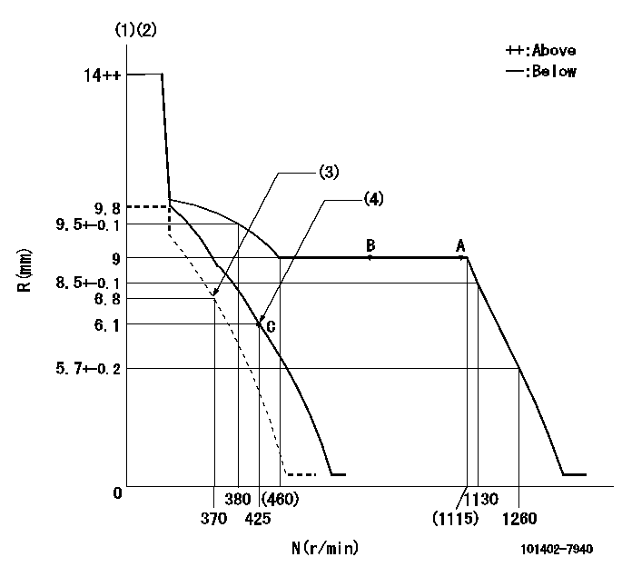
N:Pump speed
R:Rack position (mm)
(1)Target notch: K
(2)Tolerance for racks not indicated: +-0.05mm.
(3)Set idle sub-spring
(4)Main spring setting
----------
K=12
----------
----------
K=12
----------
Speed control lever angle
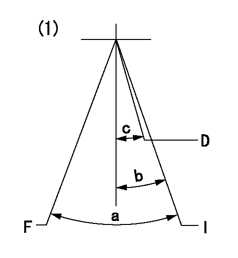
F:Full speed
I:Idle
D:Dead point
(1)With variable lever
----------
----------
a=(24deg)+-5deg b=(24deg)+-5deg c=(10deg)+-3deg
----------
----------
a=(24deg)+-5deg b=(24deg)+-5deg c=(10deg)+-3deg
Stop lever angle

N:Pump normal
S:Stop the pump.
(1)Normal
----------
----------
a=13deg+-5deg b=53deg+-5deg
----------
----------
a=13deg+-5deg b=53deg+-5deg
Timing setting

(1)Pump vertical direction
(2)Position of gear mark 'CC' at No 1 cylinder's beginning of injection
(3)B.T.D.C.: aa
(4)-
----------
aa=12deg
----------
a=(100deg)
----------
aa=12deg
----------
a=(100deg)
Information:
Install Water Pump
1. Put the gasket and water pump (1) in position in the timing gear cover. 2. Install the pointer and bolts to hold the water pump.3. Put the vee belts in position on the engine.4. Use a belt tension gauge such as Borroughs Tool Company Part No. BT-33-72C or an equivalent and make an adjustment of the vee belts. Tighten new belts until the gauge indication is 120 5. Operate the engine at high idle for a minimum of 30 minutes after Step 5. Make another adjustment of the belt tension. The correct gauge indication for used belts is 90 10. Tighten the bolts that hold the alternator.5. Fill the cooling system with coolant to the correct level.Disassemble Water Pump
a) remove water pump1. Hold the pump shaft in a vise as shown and remove the bolt and pulley (1). 2. Use tooling (A) and a press to remove the shaft, seal and impeller from housing (2) as shown.
The press must have a guard. The guard has been removed for photo illustration.
3. Remove bearing (3) from housing (2). 4. Remove spacer (4) from housing (2). 5. Use tool (B) to remove ring (5) from housing (2). Remove bearing (6) from housing (2).6. Use a press and tool (C) to remove the shaft and seal assembly from impeller (7) as shown. 7. Install the seal assembly and shaft in housing (2) as shown. Use a press and tool (C) to remove the shaft from the seal assembly. Assemble Water Pump
1 Install bearing (1) in housing (3). Use tool (A) to install ring (2) that holds bearing (1) in position. 2 Install spacer (4) in housing (3). 3 Make sure the outside diameter of bearing (5) and the bore in housing (3) are clean and dry. Install bearing (5) in housing (3). Fill the chamber area between the housing and outside diameter of bearing (5) with 7M7456 Bearing Mount. Remove the excess bearing mount from the housing. 4. Turn the pump housing over and make sure that the bores in the bearings and spacer are in alignment. Install the shaft through the bearings from the impeller side of the housing. The shaft to bearing clearance can be 0.018 mm (.0007 in.) loose to 0.008 mm (.0003 in.) tight. If it is necessary to use a press to install the shaft, make sure the inner races of the bearings have support. 5. Install pulley (6) on the shaft and tighten the bolt to a torque of 75 7 N m (55 5 lb.ft.). 6. Put a new seal assembly (7) on the shaft as shown.7. Use tool (B) and a press to install the seal assembly in housing (3). Do not use a hammer to install the seal. 8. Put tool (D) between impeller (8) and the pump housing.9. Use a press and tool (C) to install impeller (8) on the shaft until tool (D) can just be moved between the housing and impeller. 10. If