Information injection-pump assembly
BOSCH
9 400 612 157
9400612157
ZEXEL
101402-7880
1014027880
ISUZU
8972888870
8972888870
Rating:
Service parts 101402-7880 INJECTION-PUMP ASSEMBLY:
1.
_
5.
AUTOM. ADVANCE MECHANIS
6.
COUPLING PLATE
8.
_
9.
_
11.
Nozzle and Holder
8-97238-978-0
12.
Open Pre:MPa(Kqf/cm2)
18.1{185}

15.
NOZZLE SET
Cross reference number
BOSCH
9 400 612 157
9400612157
ZEXEL
101402-7880
1014027880
ISUZU
8972888870
8972888870
Zexel num
Bosch num
Firm num
Name
9 400 612 157
8972888870 ISUZU
INJECTION-PUMP ASSEMBLY
4JG1-T * K 14BC INJECTION PUMP ASSY PE4A,5A, PE
4JG1-T * K 14BC INJECTION PUMP ASSY PE4A,5A, PE
Calibration Data:
Adjustment conditions
Test oil
1404 Test oil ISO4113 or {SAEJ967d}
1404 Test oil ISO4113 or {SAEJ967d}
Test oil temperature
degC
40
40
45
Nozzle and nozzle holder
105780-8140
Bosch type code
EF8511/9A
Nozzle
105780-0000
Bosch type code
DN12SD12T
Nozzle holder
105780-2080
Bosch type code
EF8511/9
Opening pressure
MPa
17.2
Opening pressure
kgf/cm2
175
Injection pipe
Outer diameter - inner diameter - length (mm) mm 6-2-600
Outer diameter - inner diameter - length (mm) mm 6-2-600
Overflow valve
131424-0820
Overflow valve opening pressure
kPa
127
107
147
Overflow valve opening pressure
kgf/cm2
1.3
1.1
1.5
Tester oil delivery pressure
kPa
157
157
157
Tester oil delivery pressure
kgf/cm2
1.6
1.6
1.6
Direction of rotation (viewed from drive side)
Left L
Left L
Injection timing adjustment
Direction of rotation (viewed from drive side)
Left L
Left L
Injection order
1-3-4-2
Pre-stroke
mm
3.5
3.45
3.55
Beginning of injection position
Drive side NO.1
Drive side NO.1
Difference between angles 1
Cal 1-3 deg. 90 89.5 90.5
Cal 1-3 deg. 90 89.5 90.5
Difference between angles 2
Cal 1-4 deg. 180 179.5 180.5
Cal 1-4 deg. 180 179.5 180.5
Difference between angles 3
Cyl.1-2 deg. 270 269.5 270.5
Cyl.1-2 deg. 270 269.5 270.5
Injection quantity adjustment
Adjusting point
A
Rack position
10.1
Pump speed
r/min
1250
1250
1250
Average injection quantity
mm3/st.
79.5
78.5
80.5
Max. variation between cylinders
%
0
-2.5
2.5
Basic
*
Fixing the lever
*
Injection quantity adjustment_02
Adjusting point
-
Rack position
6.5+-0.5
Pump speed
r/min
500
500
500
Average injection quantity
mm3/st.
11.5
9.5
13.5
Max. variation between cylinders
%
0
-15
15
Fixing the rack
*
Remarks
Adjust only variation between cylinders; adjust governor according to governor specifications.
Adjust only variation between cylinders; adjust governor according to governor specifications.
Test data Ex:
Governor adjustment
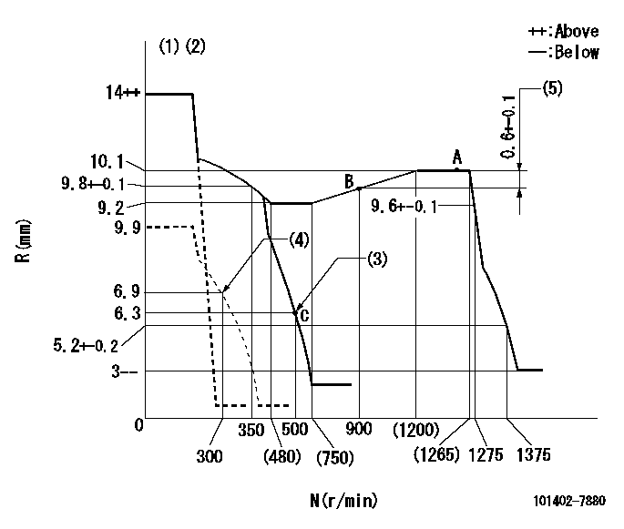
N:Pump speed
R:Rack position (mm)
(1)Target notch: K
(2)Tolerance for racks not indicated: +-0.05mm.
(3)Main spring setting
(4)Set idle sub-spring
(5)Rack difference between N = N1 and N = N2
----------
K=10 N1=1250r/min N2=900r/min
----------
----------
K=10 N1=1250r/min N2=900r/min
----------
Speed control lever angle
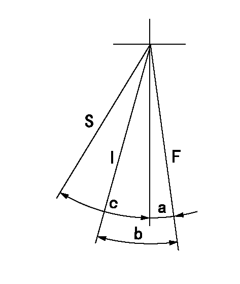
F:Full speed
I:Idle
S:Stop
----------
----------
a=8deg+-5deg b=24deg+-5deg c=31deg+-3deg
----------
----------
a=8deg+-5deg b=24deg+-5deg c=31deg+-3deg
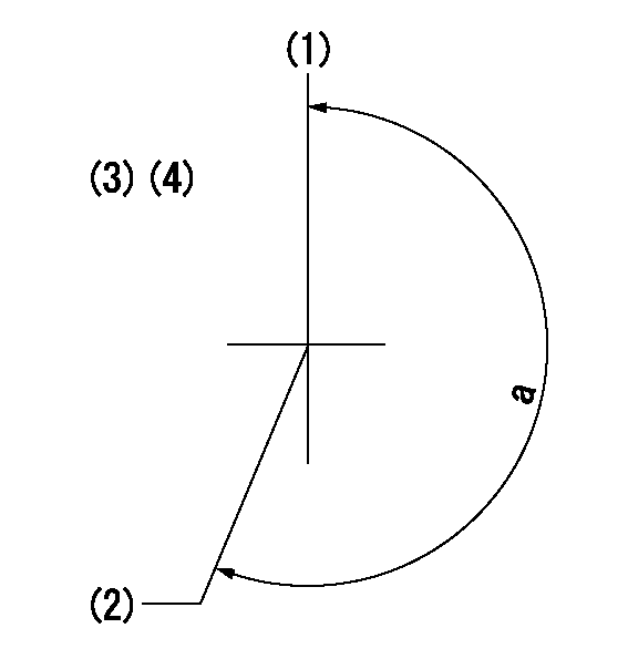
Stop lever angle
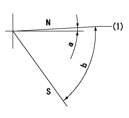
N:Pump normal
S:Stop the pump.
(1)Normal
----------
----------
a=0deg+-5deg b=53deg+-5deg
----------
----------
a=0deg+-5deg b=53deg+-5deg
Timing setting
(1)Pump vertical direction
(2)Position of gear mark 'W' at No 1 cylinder's beginning of injection
(3)B.T.D.C.: aa
(4)-
----------
aa=6deg
----------
a=(210deg)
----------
aa=6deg
----------
a=(210deg)
Information:
White Smoke
Recommended Procedure
1. Cold Outside Temperatures ... When the air outside is cold, the cylinder temperature is cooler. Not all the fuel will burn in the cylinders. The fuel which does not burn comes out the exhaust as white smoke. White smoke is normal in cold temperatures until the engine operates long enough to become warm. There will be less white smoke if No. 1 diesel fuel is used.2. Long Idle Periods ... When an engine runs at idle speed for a long period of time, the cylinders cool and all of the fuel does not burn. Do not idle an engine for a long period of time. Stop an engine when it is not in use. If long idle periods are necessary, use No. 1 diesel fuel.3. Low Quality Fuel ... Test the engine using fuel according to recommendations by Caterpillar.4. Air in Fuel System ... With air in the fuel system the engine will normally be difficult to start, run rough and release a large amount of white smoke. To remove the air from the fuel system open the manual bleed valve on the fuel injection pump housing. Operate the priming pump until the flow of fuel from the manual bleed valve is free of air. Close the manual bleed valve and fasten the fuel priming pump. Start the engine. If the engine still does not run smooth or releases a large amount of white smoke, loosen the fuel line nuts one at a time at the cylinder heads, and permit the fuel to come out until it is free of air. Tighten the fuel line nuts. If air is not removed in this way, put 35 kPa (5 psi) of air pressure to the fuel tank.
Do not use more than 55 kPa (8 psi) of air pressure in the fuel tank or damage to the tank may result.
Check for leakage at the connections between the fuel tank and the fuel transfer pump. If leaks are found, tighten the connections or replace the lines. If there are no visual leaks, remove the fuel supply line from the tank and connect it to an outside fuel supply. If this corrects the problem, the suction line (standpipe) inside the fuel tank has a leak.5. Fuel Injection Timing Not Correct ... Check and make necessary adjustments as per Testing and Adjusting section of this Service Manual.6. Automatic Timing Advance Does Not Operate Correctly ... Check with engine warm. Use the 8T5300 Timing Indicator Group to check the automatic timing advance unit. Check to see that the advance is smooth and that the amount of advance is correct. See Fuel System of the Testing and Adjusting section of this Service Manual for the subject Checking Engine Timing And Automatic Timing Advance Unit With 8T5300 Timing Indicator Group. If the timing indicator is not available, make rapid "acceleration" (increase in speed) from low idle to high idle. Engine must have smooth acceleration. A timing advance that does not operate correctly