Information injection-pump assembly
ZEXEL
101402-7811
1014027811
ISUZU
8972541181
8972541181
Rating:
Service parts 101402-7811 INJECTION-PUMP ASSEMBLY:
1.
_
5.
AUTOM. ADVANCE MECHANIS
6.
COUPLING PLATE
8.
_
9.
_
11.
Nozzle and Holder
12.
Open Pre:MPa(Kqf/cm2)
15.
NOZZLE SET
Cross reference number
ZEXEL
101402-7811
1014027811
ISUZU
8972541181
8972541181
Zexel num
Bosch num
Firm num
Name
Calibration Data:
Adjustment conditions
Test oil
1404 Test oil ISO4113 or {SAEJ967d}
1404 Test oil ISO4113 or {SAEJ967d}
Test oil temperature
degC
40
40
45
Nozzle and nozzle holder
105780-8140
Bosch type code
EF8511/9A
Nozzle
105780-0000
Bosch type code
DN12SD12T
Nozzle holder
105780-2080
Bosch type code
EF8511/9
Opening pressure
MPa
17.2
Opening pressure
kgf/cm2
175
Injection pipe
Outer diameter - inner diameter - length (mm) mm 6-2-600
Outer diameter - inner diameter - length (mm) mm 6-2-600
Overflow valve
134424-4120
Overflow valve opening pressure
kPa
255
221
289
Overflow valve opening pressure
kgf/cm2
2.6
2.25
2.95
Tester oil delivery pressure
kPa
255
255
255
Tester oil delivery pressure
kgf/cm2
2.6
2.6
2.6
Direction of rotation (viewed from drive side)
Right R
Right R
Injection timing adjustment
Direction of rotation (viewed from drive side)
Right R
Right R
Injection order
1-3-4-2
Pre-stroke
mm
4.2
4.15
4.25
Beginning of injection position
Drive side NO.1
Drive side NO.1
Difference between angles 1
Cal 1-3 deg. 90 89.5 90.5
Cal 1-3 deg. 90 89.5 90.5
Difference between angles 2
Cal 1-4 deg. 180 179.5 180.5
Cal 1-4 deg. 180 179.5 180.5
Difference between angles 3
Cyl.1-2 deg. 270 269.5 270.5
Cyl.1-2 deg. 270 269.5 270.5
Injection quantity adjustment
Adjusting point
A
Rack position
10
Pump speed
r/min
1100
1100
1100
Average injection quantity
mm3/st.
85.5
84.4
86.6
Max. variation between cylinders
%
0
-2
2
Basic
*
Fixing the lever
*
Boost pressure
kPa
93.3
93.3
Boost pressure
mmHg
700
700
Injection quantity adjustment_02
Adjusting point
-
Rack position
7.7+-0.5
Pump speed
r/min
475
475
475
Average injection quantity
mm3/st.
8.8
7.4
10.2
Max. variation between cylinders
%
0
-14
14
Fixing the rack
*
Boost pressure
kPa
0
0
0
Boost pressure
mmHg
0
0
0
Remarks
Adjust only variation between cylinders; adjust governor according to governor specifications.
Adjust only variation between cylinders; adjust governor according to governor specifications.
Injection quantity adjustment_03
Adjusting point
E
Rack position
10.2++
Pump speed
r/min
100
100
100
Average injection quantity
mm3/st.
120
115
125
Fixing the lever
*
Boost pressure
kPa
0
0
0
Boost pressure
mmHg
0
0
0
Rack limit
*
Boost compensator adjustment
Pump speed
r/min
650
650
650
Rack position
8.7
Boost pressure
kPa
40
36
44
Boost pressure
mmHg
300
270
330
Boost compensator adjustment_02
Pump speed
r/min
650
650
650
Rack position
9
Boost pressure
kPa
80
73.3
86.7
Boost pressure
mmHg
600
550
650
Test data Ex:
Governor adjustment
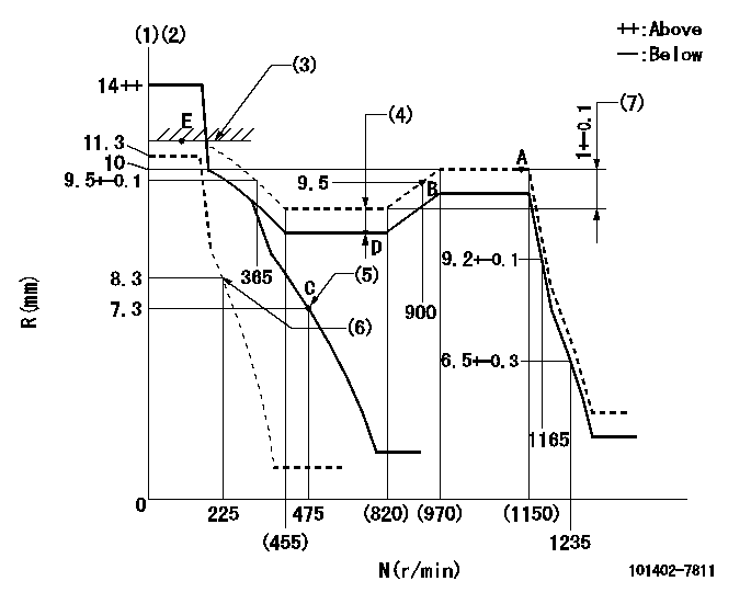
N:Pump speed
R:Rack position (mm)
(1)Target notch: K
(2)Tolerance for racks not indicated: +-0.05mm.
(3)RACK LIMIT
(4)Boost compensator stroke: BCL
(5)Main spring setting
(6)Set idle sub-spring
(7)Rack difference between N = N1 and N = N2
----------
K=9 BCL=0.3+-0.1mm N1=1100r/min N2=650r/min
----------
----------
K=9 BCL=0.3+-0.1mm N1=1100r/min N2=650r/min
----------
Speed control lever angle

F:Full speed
I:Idle
(1)Stopper bolt setting
----------
----------
a=5deg+-5deg b=20deg+-5deg
----------
----------
a=5deg+-5deg b=20deg+-5deg
Stop lever angle
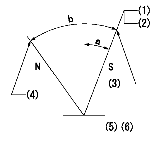
N:Pump normal
S:Stop the pump.
(1)Pump speed aa and rack position bb (to be sealed at delivery)
(2)Normal stop
(3)Stopper bolt setting
(4)Stopper bolt setting
(5)The stop lever does not have to return to the stop position (but set screw at rack position = cc).
(6)-
----------
aa=0r/min bb=1-0.5mm cc=1-0.5mm
----------
a=10deg+-5deg b=(55deg)
----------
aa=0r/min bb=1-0.5mm cc=1-0.5mm
----------
a=10deg+-5deg b=(55deg)
0000001501 TAMPER PROOF

Tamperproofing-equipped boost compensator cover installation procedure
(A) After adjusting the boost compensator, tighten the bolts to remove the heads.
(1)Before adjusting the governor and the boost compensator, tighten the screw to the specified torque.
(Tightening torque T = T1 maximum)
(2)After adjusting the governor and the boost compensator, tighten to the specified torque to break off the bolt heads.
(Tightening torque T = T2 maximum)
----------
T1=2.5N-m(0.25kgf-m) T2=2.9~4.4N-m(0.3~0.45kgf-m)
----------
----------
T1=2.5N-m(0.25kgf-m) T2=2.9~4.4N-m(0.3~0.45kgf-m)
----------
Timing setting

(1)Pump vertical direction
(2)Position of gear mark 'CC' at No 1 cylinder's beginning of injection
(3)B.T.D.C.: aa
(4)-
----------
aa=7deg
----------
a=(100deg)
----------
aa=7deg
----------
a=(100deg)
Information:
(1) Bore in the rear bearing for the camshaft (new) ... 60.325 0.013 mm (2.3750 .0005 in) Diameter of rear bearing surface (journal) of the camshaft (new) ... 60.249 0.013 mm (2.3720 .0005 in)Maximum permissible clearance between the bearing and the camshaft bearing surface (journal) (worn) ... 0.15 mm (.006 in)(2) Torque for screws that hold sleeve control levers ... 2.8 0.2 N m (24 2 lb in)(3) Bore in the housing for the fuel control shaft (new) ... 8.999 0.013 mm (.3543 .0005 in) Diameter of sleeve control shaft (new) ... 8.966 0.008 mm (.3530 .0003 in)Maximum permissible clearance between the bore in the housing and the sleeve control shaft (worn) ... 0.08 mm (.003 in)(4) End play for camshaft with sleeve installed (new) ... 0.58 0.46 mm (.023 .018 in) When installing sleeve on end of camshaft, support the camshaft to prevent damage to parts inside of injection pump and governor housing.(5) Bore in the front bearing for the camshaft (new) ... 25.413 0.013 mm (1.0005 .0005 in) Diameter of front bearing surface (journal) of the camshaft (new) ... 25.375 0.013 mm (.9990 .0005 in)Maximum permissible clearance between the bearing and the camshaft bearing surface (journal) (worn) ... 0.10 mm (.004 in) (6) Torque for bushing ... 82 7 N m (60 5 lb ft)(7) Crossover levers. For adjustment of crossover levers, see the Testing And Adjusting Section.(8) Torque for screws that hold crossover levers ... 2.8 0.2 N m (24 2 lb in)(9 and 10) Fuel control shafts.(11) Dowel pin (linkage between crossover levers).(12) Distance guide pin extends into bore ... 1.20 0.10 mm (.047 .004 in) Install guide pin with slot toward the top of the lifter bore.(13) 9N5862 Spring for injection pump: Length under test force ... 35.13 mm (1.383 in)Test force ... 56.7 6.6 N (12.4 1.4 lb)Free length after test ... 40.80 mm (1.606 in)Outside diameter ... 18.49 mm (.728 in)A. Reverse Flow Check Valve (RFC).B. Orificed Delivery Valve (ODV).C. Orificed Delivery Valve-Lo Volume (ODV).D. Orificed Reverse Flow Check Valve (ORFC).