Information injection-pump assembly
BOSCH
9 400 613 493
9400613493
ZEXEL
101402-7801
1014027801
ISUZU
8972574731
8972574731

Rating:
Service parts 101402-7801 INJECTION-PUMP ASSEMBLY:
1.
_
5.
AUTOM. ADVANCE MECHANIS
6.
COUPLING PLATE
8.
_
9.
_
11.
Nozzle and Holder
8-97257-496-0
12.
Open Pre:MPa(Kqf/cm2)
18.1{185}
15.
NOZZLE SET
Cross reference number
BOSCH
9 400 613 493
9400613493
ZEXEL
101402-7801
1014027801
ISUZU
8972574731
8972574731
Zexel num
Bosch num
Firm num
Name
101402-7801
9 400 613 493
8972574731 ISUZU
INJECTION-PUMP ASSEMBLY
4BG1 K 14BD INJECTION PUMP ASSY PE4AD PE
4BG1 K 14BD INJECTION PUMP ASSY PE4AD PE
Calibration Data:
Adjustment conditions
Test oil
1404 Test oil ISO4113 or {SAEJ967d}
1404 Test oil ISO4113 or {SAEJ967d}
Test oil temperature
degC
40
40
45
Nozzle and nozzle holder
105780-8140
Bosch type code
EF8511/9A
Nozzle
105780-0000
Bosch type code
DN12SD12T
Nozzle holder
105780-2080
Bosch type code
EF8511/9
Opening pressure
MPa
17.2
Opening pressure
kgf/cm2
175
Injection pipe
Outer diameter - inner diameter - length (mm) mm 6-2-600
Outer diameter - inner diameter - length (mm) mm 6-2-600
Overflow valve
134424-4120
Overflow valve opening pressure
kPa
255
221
289
Overflow valve opening pressure
kgf/cm2
2.6
2.25
2.95
Tester oil delivery pressure
kPa
255
255
255
Tester oil delivery pressure
kgf/cm2
2.6
2.6
2.6
Direction of rotation (viewed from drive side)
Right R
Right R
Injection timing adjustment
Direction of rotation (viewed from drive side)
Right R
Right R
Injection order
1-3-4-2
Pre-stroke
mm
3.6
3.55
3.65
Beginning of injection position
Drive side NO.1
Drive side NO.1
Difference between angles 1
Cal 1-3 deg. 90 89.5 90.5
Cal 1-3 deg. 90 89.5 90.5
Difference between angles 2
Cal 1-4 deg. 180 179.5 180.5
Cal 1-4 deg. 180 179.5 180.5
Difference between angles 3
Cyl.1-2 deg. 270 269.5 270.5
Cyl.1-2 deg. 270 269.5 270.5
Injection quantity adjustment
Adjusting point
A
Rack position
10
Pump speed
r/min
1400
1400
1400
Average injection quantity
mm3/st.
110
108.4
111.6
Max. variation between cylinders
%
0
-2.5
2.5
Basic
*
Fixing the lever
*
Injection quantity adjustment_02
Adjusting point
C
Rack position
6+-0.5
Pump speed
r/min
260
260
260
Average injection quantity
mm3/st.
14
12.7
15.3
Max. variation between cylinders
%
0
-14
14
Fixing the rack
*
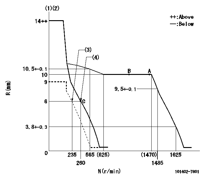
Test data Ex:
Governor adjustment

N:Pump speed
R:Rack position (mm)
(1)Target notch: K
(2)Tolerance for racks not indicated: +-0.05mm.
(3)Set idle sub-spring
(4)Main spring setting
----------
K=12
----------
----------
K=12
----------
Speed control lever angle

F:Full speed
I:Idle
(1)Stopper bolt setting
----------
----------
a=(15deg)+-5deg b=(29deg)+-5deg
----------
----------
a=(15deg)+-5deg b=(29deg)+-5deg
Stop lever angle

N:Pump normal
S:Stop the pump.
(1)Normal
----------
----------
a=19deg+-5deg b=53deg+-5deg
----------
----------
a=19deg+-5deg b=53deg+-5deg
Timing setting

(1)Pump vertical direction
(2)Position of gear mark 'CC' at No 1 cylinder's beginning of injection
(3)B.T.D.C.: aa
(4)-
----------
aa=20deg
----------
a=(95deg)
----------
aa=20deg
----------
a=(95deg)
Information:
Illustration 8 g01455580
(6) 294-3395 Exhaust Support Assembly
Make four mounting holes for 294-3395 Exhaust Support Assembly (6) in the location (designated with a circle) which is shown in Illustration 8.
Illustration 9 g01456256
(17) 8T-4223 Hard Washers (18) 8T-4244 Nuts (19) 8T-4648 Bolt (20) 8T-4956 Bolt (21) 8T-6868 Bolts
Install exhaust support assembly (6) by using two 8T-6868 Bolts (21), one 8T-4648 Bolt (19), one 8T-4956 Bolt (20), four 8T-4223 Hard Washers (17), and four 8T-4244 Nuts (18). Refer to Illustration 9.
Illustration 10 g01456263
(9) 295-3044 Exhaust Support Groups (Lower half)
Remove the upper clamp from each 295-3044 Exhaust Support Group (9) by removing the two bolts and two hard washers. Keep the four bolts, the four hard washers, and the two upper clamps together. These parts will be reinstalled in Step 15.
Use four 8T-4956 Bolts (20) and four 8T-4223 Hard Washers (17) to install both 295-3044 Exhaust Support Groups (9) to exhaust support assembly (6). Refer to Illustration 10.
Illustration 11 g01456281
(5) 294-3065 Diesel Particulate Filter Group
To facilitate handling, remove the filter units from 294-3065 Diesel Particulate Filter Group (5) by removing the two clamps (including gaskets) closest to the rectangular intake manifold. Place the filter units, clamps, and gaskets aside.Note: Handle the removed filter units with extra care, as the internal structure is subject to damage due to impact, dropping, etc. Do not allow the inside of the filter units to get wet.
Install 294-3065 Diesel Particulate Filter Group (5) by aligning the mounting holes in the intake manifold with the mounting holes in the welded exhaust support assembly (7). Secure the intake manifold to the exhaust support assembly by using two 8T-4956 Bolts (20), two 8T-4223 Hard Washers (17), and two 8T-4244 Nuts (18). Refer to Illustration 11.
Reattach the lower filter unit to the intake manifold by reinstalling the clamp and the gasket that was removed in Step 12. Repeat for the upper filter unit.
Illustration 12 g01456285
Align the mounting holes in the upper half of 295-3044 Exhaust Support Group (9) with the mounting holes in the lower half of the exhaust support group (9). Reinstall the two bolts (9a) and the two hard washers (9b). Repeat for the other exhaust support group (9). Refer to Illustration 12.
Connect the straight end of exhaust tube assembly (8) to the manifold inlet pipe of the Diesel Particulate Filter Group. Use one 190-5341 Clamp (3)
Have questions with 101402-7801?
Group cross 101402-7801 ZEXEL
Isuzu
101402-7801
9 400 613 493
8972574731
INJECTION-PUMP ASSEMBLY
4BG1
4BG1