Information injection-pump assembly
BOSCH
F 019 Z10 103
f019z10103
ZEXEL
101402-7761
1014027761
ISUZU
8972544291
8972544291
Rating:
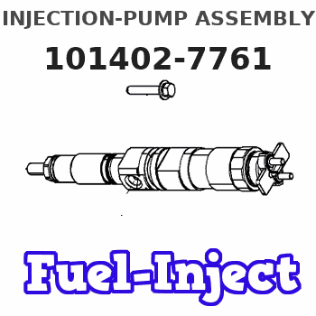
Service parts 101402-7761 INJECTION-PUMP ASSEMBLY:
1.
_
5.
AUTOM. ADVANCE MECHANIS
6.
COUPLING PLATE
8.
_
9.
_
11.
Nozzle and Holder
12.
Open Pre:MPa(Kqf/cm2)
18.1{185}
15.
NOZZLE SET
Cross reference number
BOSCH
F 019 Z10 103
f019z10103
ZEXEL
101402-7761
1014027761
ISUZU
8972544291
8972544291
Zexel num
Bosch num
Firm num
Name
101402-7761
F 019 Z10 103
8972544291 ISUZU
INJECTION-PUMP ASSEMBLY
4BG1-T K 14BC INJECTION PUMP ASSY PE4A,5A, PE
4BG1-T K 14BC INJECTION PUMP ASSY PE4A,5A, PE
Calibration Data:
Adjustment conditions
Test oil
1404 Test oil ISO4113 or {SAEJ967d}
1404 Test oil ISO4113 or {SAEJ967d}
Test oil temperature
degC
40
40
45
Nozzle and nozzle holder
105780-8140
Bosch type code
EF8511/9A
Nozzle
105780-0000
Bosch type code
DN12SD12T
Nozzle holder
105780-2080
Bosch type code
EF8511/9
Opening pressure
MPa
17.2
Opening pressure
kgf/cm2
175
Injection pipe
Outer diameter - inner diameter - length (mm) mm 6-2-600
Outer diameter - inner diameter - length (mm) mm 6-2-600
Overflow valve
131424-4920
Overflow valve opening pressure
kPa
127
107
147
Overflow valve opening pressure
kgf/cm2
1.3
1.1
1.5
Tester oil delivery pressure
kPa
157
157
157
Tester oil delivery pressure
kgf/cm2
1.6
1.6
1.6
Direction of rotation (viewed from drive side)
Right R
Right R
Injection timing adjustment
Direction of rotation (viewed from drive side)
Right R
Right R
Injection order
1-3-4-2
Pre-stroke
mm
3.4
3.35
3.45
Beginning of injection position
Drive side NO.1
Drive side NO.1
Difference between angles 1
Cal 1-3 deg. 90 89.5 90.5
Cal 1-3 deg. 90 89.5 90.5
Difference between angles 2
Cal 1-4 deg. 180 179.5 180.5
Cal 1-4 deg. 180 179.5 180.5
Difference between angles 3
Cyl.1-2 deg. 270 269.5 270.5
Cyl.1-2 deg. 270 269.5 270.5
Injection quantity adjustment
Adjusting point
A
Rack position
8.8
Pump speed
r/min
1050
1050
1050
Average injection quantity
mm3/st.
94
92.9
95.1
Max. variation between cylinders
%
0
-2
2
Basic
*
Fixing the lever
*
Injection quantity adjustment_02
Adjusting point
-
Rack position
6.1+-0.5
Pump speed
r/min
450
450
450
Average injection quantity
mm3/st.
8.8
7.4
10.2
Max. variation between cylinders
%
0
-14
14
Fixing the rack
*
Remarks
Adjust only variation between cylinders; adjust governor according to governor specifications.
Adjust only variation between cylinders; adjust governor according to governor specifications.
Injection quantity adjustment_03
Adjusting point
D
Rack position
9++
Pump speed
r/min
100
100
100
Average injection quantity
mm3/st.
125
120
130
Fixing the lever
*
Rack limit
*
Test data Ex:
Governor adjustment
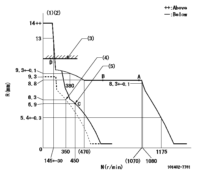
N:Pump speed
R:Rack position (mm)
(1)Target notch: K
(2)Tolerance for racks not indicated: +-0.05mm.
(3)RACK LIMIT
(4)Set idle sub-spring
(5)Main spring setting
----------
K=6
----------
----------
K=6
----------
Speed control lever angle
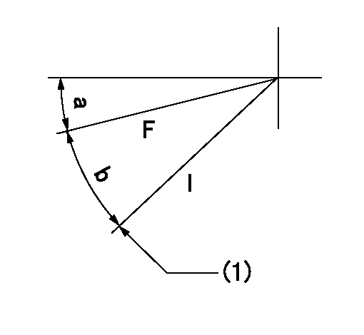
F:Full speed
I:Idle
(1)Stopper bolt setting
----------
----------
a=2deg+-5deg b=21deg+-5deg
----------
----------
a=2deg+-5deg b=21deg+-5deg
Stop lever angle

N:Pump normal
S:Stop the pump.
(1)Normal
----------
----------
a=4.5deg+-5deg b=53deg+-5deg
----------
----------
a=4.5deg+-5deg b=53deg+-5deg
Timing setting

(1)Pump vertical direction
(2)Position of gear mark 'CC' at No 1 cylinder's beginning of injection
(3)B.T.D.C.: aa
(4)-
----------
aa=9deg
----------
a=(100deg)
----------
aa=9deg
----------
a=(100deg)
Information:
preparatory steps: a) remove rocker shaft assemblyb) remove water temperature regulator1. Disconnect the fuel ratio control sensing line (1). Remove the sensing line clamp bolt (2). 2. Disconnect the turbocharger oil supply line (3) and the oil drain line (4).3. Remove the fuel injection lines (5) and install protective caps.4. Disconnect the air compressor water return line (8). 5. Remove the retaining bolts (7) and the fan drive mounting bracket (6).6. Remove the cylinder head retaining bolts. Attach a hoist and remove the cylinder head assembly-weight 240 lbs. (109,1 kg).Install Cylinder Head Assembly
1. Thoroughly clean the sealing surfaces of the cylinder head and cylinder block. Position a new head gasket on the engine and install the cylinder head assembly.2. Install the push rods and rocker shaft assembly.3. Coat the threads of the cylinder head retaining bolts with 4S9416 Anti-Seize Compound. Install bolts and washers, and tighten them in the following sequence: 1 - Tighten all numbered bolts in numerical order to 115 lb. ft. (15,9 mkg).2 - Retighten all numbered bolts in numerical order to 175 5 lb. ft. (24,2 0,7 mkg).3 - Finally, retighten all numbered bolts (hand torque only) in numerical order to 175 5 lb. ft. (24,2 0,7 mkg).4 - Tighten all lettered bolts in alphabetical order to 22 lb. ft. (3,0 mkg).5 - Retighten all lettered bolts in alphabetical order to 32 5 lb. ft. (4,4 0,7 mkg).6 - Finally, retighten all lettered bolts (hand torque only) in alphabetical order to 32 5 lb. ft. (4,4 0,7 mkg).4. Adjust the inlet and exhaust valve clearance as covered in INSTALL ROCKER SHAFT ASSEMBLY AND PUSH RODS.5. Connect the air compressor water return line.6. Install the fuel lines and tighten the retaining nuts to 30 5 lb. ft. (4,1 0,7 mkg).7. Connect the turbocharger oil supply line and the oil drain line.8. Connect the fuel ratio control sensing line and install the sensing line clamp bolt.9. Install the fan drive mounting bracket and retaining bolts.concluding steps: a) install water temperature regulatorb) install valve cover
1. Thoroughly clean the sealing surfaces of the cylinder head and cylinder block. Position a new head gasket on the engine and install the cylinder head assembly.2. Install the push rods and rocker shaft assembly.3. Coat the threads of the cylinder head retaining bolts with 4S9416 Anti-Seize Compound. Install bolts and washers, and tighten them in the following sequence: 1 - Tighten all numbered bolts in numerical order to 115 lb. ft. (15,9 mkg).2 - Retighten all numbered bolts in numerical order to 175 5 lb. ft. (24,2 0,7 mkg).3 - Finally, retighten all numbered bolts (hand torque only) in numerical order to 175 5 lb. ft. (24,2 0,7 mkg).4 - Tighten all lettered bolts in alphabetical order to 22 lb. ft. (3,0 mkg).5 - Retighten all lettered bolts in alphabetical order to 32 5 lb. ft. (4,4 0,7 mkg).6 - Finally, retighten all lettered bolts (hand torque only) in alphabetical order to 32 5 lb. ft. (4,4 0,7 mkg).4. Adjust the inlet and exhaust valve clearance as covered in INSTALL ROCKER SHAFT ASSEMBLY AND PUSH RODS.5. Connect the air compressor water return line.6. Install the fuel lines and tighten the retaining nuts to 30 5 lb. ft. (4,1 0,7 mkg).7. Connect the turbocharger oil supply line and the oil drain line.8. Connect the fuel ratio control sensing line and install the sensing line clamp bolt.9. Install the fan drive mounting bracket and retaining bolts.concluding steps: a) install water temperature regulatorb) install valve cover
Have questions with 101402-7761?
Group cross 101402-7761 ZEXEL
Isuzu
101402-7761
F 019 Z10 103
8972544291
INJECTION-PUMP ASSEMBLY
4BG1-T
4BG1-T
