Information injection-pump assembly
BOSCH
9 400 613 978
9400613978
ZEXEL
101402-7681
1014027681
ISUZU
8972393730
8972393730
Rating:
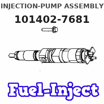
Service parts 101402-7681 INJECTION-PUMP ASSEMBLY:
1.
_
5.
AUTOM. ADVANCE MECHANIS
6.
COUPLING PLATE
8.
_
9.
_
11.
Nozzle and Holder
12.
Open Pre:MPa(Kqf/cm2)
18.1(185)
15.
NOZZLE SET
Cross reference number
BOSCH
9 400 613 978
9400613978
ZEXEL
101402-7681
1014027681
ISUZU
8972393730
8972393730
Zexel num
Bosch num
Firm num
Name
101402-7681
9 400 613 978
8972393730 ISUZU
INJECTION-PUMP ASSEMBLY
4BG1-T K 14BC INJECTION PUMP ASSY PE4A,5A, PE
4BG1-T K 14BC INJECTION PUMP ASSY PE4A,5A, PE
Calibration Data:
Adjustment conditions
Test oil
1404 Test oil ISO4113 or {SAEJ967d}
1404 Test oil ISO4113 or {SAEJ967d}
Test oil temperature
degC
40
40
45
Nozzle and nozzle holder
105780-8140
Bosch type code
EF8511/9A
Nozzle
105780-0000
Bosch type code
DN12SD12T
Nozzle holder
105780-2080
Bosch type code
EF8511/9
Opening pressure
MPa
17.2
Opening pressure
kgf/cm2
175
Injection pipe
Outer diameter - inner diameter - length (mm) mm 6-2-600
Outer diameter - inner diameter - length (mm) mm 6-2-600
Overflow valve
131424-4920
Overflow valve opening pressure
kPa
127
127
127
Overflow valve opening pressure
kgf/cm2
1.3
1.3
1.3
Tester oil delivery pressure
kPa
157
157
157
Tester oil delivery pressure
kgf/cm2
1.6
1.6
1.6
Direction of rotation (viewed from drive side)
Right R
Right R
Injection timing adjustment
Direction of rotation (viewed from drive side)
Right R
Right R
Injection order
1-3-4-2
Pre-stroke
mm
3.2
3.15
3.25
Beginning of injection position
Drive side NO.1
Drive side NO.1
Difference between angles 1
Cal 1-3 deg. 90 89.5 90.5
Cal 1-3 deg. 90 89.5 90.5
Difference between angles 2
Cal 1-4 deg. 180 179.5 180.5
Cal 1-4 deg. 180 179.5 180.5
Difference between angles 3
Cyl.1-2 deg. 270 269.5 270.5
Cyl.1-2 deg. 270 269.5 270.5
Injection quantity adjustment
Adjusting point
A
Rack position
8.8
Pump speed
r/min
1050
1050
1050
Average injection quantity
mm3/st.
83.5
82.4
84.6
Max. variation between cylinders
%
0
-2
2
Basic
*
Fixing the lever
*
Injection quantity adjustment_02
Adjusting point
C
Rack position
6+-0.5
Pump speed
r/min
475
475
475
Average injection quantity
mm3/st.
8.8
7.4
10.2
Max. variation between cylinders
%
0
-14
14
Fixing the rack
*
Injection quantity adjustment_03
Adjusting point
D
Rack position
-
Pump speed
r/min
100
100
100
Average injection quantity
mm3/st.
125
120
130
Fixing the lever
*
Rack limit
*
Test data Ex:
Governor adjustment
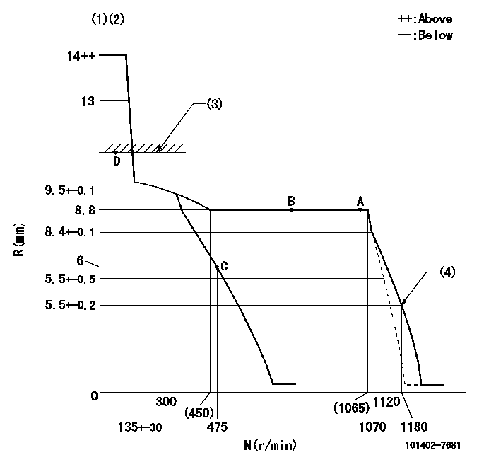
N:Pump speed
R:Rack position (mm)
(1)Target notch: K
(2)Tolerance for racks not indicated: +-0.05mm.
(3)RACK LIMIT
(4)Set idle sub-spring
----------
K=6
----------
----------
K=6
----------
Speed control lever angle
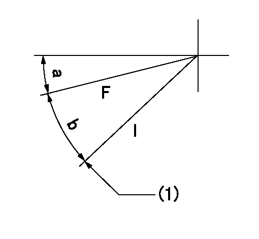
F:Full speed
I:Idle
(1)Stopper bolt setting
----------
----------
a=1deg+-5deg b=20deg+-5deg
----------
----------
a=1deg+-5deg b=20deg+-5deg
Stop lever angle

N:Pump normal
S:Stop the pump.
(1)Normal
----------
----------
a=4.5deg+-5deg b=53deg+-5deg
----------
----------
a=4.5deg+-5deg b=53deg+-5deg
Timing setting

(1)Pump vertical direction
(2)Position of gear mark 'CC' at No 1 cylinder's beginning of injection
(3)B.T.D.C.: aa
(4)-
----------
aa=14deg
----------
a=(100deg)
----------
aa=14deg
----------
a=(100deg)
Information:
Camshaft
When reconditioning an engine, check the diameter of the camshaft bearing journals and the camshaft lobe height.Camshaft bearing journals have a diameter of 2.5000 .0005 in. (63.500 0.013) and the minimum diameter worn is 2.4970 in. (63.424 mm).To measure height (B) of camshaft lobes, use the following procedures: 1. Measure base circle (C) of one exhaust and one intake lobe. Make a record of each dimension.2. Add lobe lift dimension (A) to each base circle measurement. The lobe lift dimension (A) is .3071 in. (7.800 mm) for the exhaust lobe and .3077 in. (7.816 mm) for the intake lobe.3. The minimum height of lobe (B) is .025 in. (0.64 mm) less than the dimension found in Step 2.Example of finding the height of a lobe:Base circle (C) ... 1.8200 in.(46.228 mm)Add lobe lift (A) ... .3077 in.(7.816 mm)Lobe height (B) ... 2.1277 in.(54.044 mm)Maximum wear of lobe ... .025 in.(0.64 mm)Minimum height of lobe ... 2.1027 in.(53.409 mm)
CAMSHAFT LOBE
A. Lobe lift. B. Lobe height. C. Base circle.With camshaft installed in the cylinder block, check end play. End play with new components should be .007 .003 in. (0.18 0.08 mm). The maximum permissible end play is .020 in. (0.51 mm).Camshaft Followers
Use an 8S2293 Magnet to remove the cam followers.
REMOVING CAM FOLLOWERSCam followers establish a wear pattern with the camshaft lobes. Identify and reinstall the followers in the same location from which they were removed. Dishing or circular wear pattern is allowed on the cam follower face, providing the wear face keeps a polished appearance. Replace the follower if the wear face is rough or shows signs of scuffing. A new follower can be used with an old camshaft, providing the lobe is in good condition. Put engine oil on the cam followers and the camshaft lobes before installing the cam followers. Use new cam followers with a new camshaft.Camshaft Gears
1100 and 3100 Engines With Fuel Pump Camshaft Mounted Timing Advance
1. Use a 1P2320 Puller to remove the camshaft small outer gear.
PULLING SMALL GEAR (Typical Example)2. Remove the spacer immediately behind the gear.3. Use a 1P2321 Puller to remove the camshaft large inner gear.
PULLING LARGE GEAR (Typical Example)4. To install, heat both gears to a maximum temperature of 600° F. (315° C).5. Align keyway of large gear with key in camshaft. Install large inner gear on camshaft with timing mark on gear aligned with timing mark on crankshaft gear.6. Install the spacer and small outer gear.
Do not drive gears onto camshaft. Serious damage can result to camshaft or camshaft thrust pin.
Engines With Engine Camshaft Mounted Timing Advance
1. Remove screw (1) and washer (2) from end of camshaft.
REMOVING TIMING ADVANCE RETAINING SCREW
1. Screw. 2. Washer.2. Remove timing advance unit from the camshaft.3. Install puller (A), with spacer (C) over the shaft in the camshaft and spacer (B) on spacer (C) as shown and remove the gear from the camshaft.
REMOVING GEAR (Typical Example)
A. 1P2321 Puller. B. 8S5579 Spacer. C. 9S9155 Spacer.To install the gear use the following procedure:1.
Have questions with 101402-7681?
Group cross 101402-7681 ZEXEL
Isuzu
Isuzu
Isuzu
101402-7681
9 400 613 978
8972393730
INJECTION-PUMP ASSEMBLY
4BG1-T
4BG1-T
