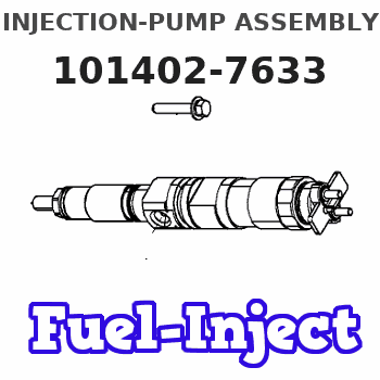
Information injection-pump assembly
BOSCH
9 400 613 198
9400613198
ZEXEL
101402-7633
1014027633
ISUZU
8972278281
8972278281

Rating:
Service parts 101402-7633 INJECTION-PUMP ASSEMBLY:
1.
_
5.
AUTOM. ADVANCE MECHANIS
6.
COUPLING PLATE
8.
_
9.
_
11.
Nozzle and Holder
12.
Open Pre:MPa(Kqf/cm2)
18.1{185}
15.
NOZZLE SET
Cross reference number
Zexel num
Bosch num
Firm num
Name
9 400 613 198
8972278281 ISUZU
INJECTION-PUMP ASSEMBLY
4BG1-T * K 14BC PE4A,5A, PE
4BG1-T * K 14BC PE4A,5A, PE
Information:
TIMING PIN AND PULLER INSTALLED (Typical Example)
1. FT887 Timing Pin. (Fabricated Tool.) 2. 9S8520 Puller Group.5. Install the 1P2320 Puller and remove the camshaft small outer gear.
PULLING SMALL OUTER GEAR6. Remove the spacer immediately behind the gear.7. Install the 1P2321 Puller and remove the camshaft large inner gear.
PULLING LARGE INNER GEARInstall Camshaft Gears
1. Heat both gears to a maximum temperature of 600° F (315° C) before installing on camshaft.2. Align keyway of large inner gear with key in camshaft. Install large inner gear on camshaft with timing mark on gear aligned with timing mark on crankshaft gear.
TIMING MARKS3. Install the spacer and small outer gear on the camshaft.
Do not drive gears onto camshaft. Serious damage can result to camshaft or camshaft thrust pin.
4. Position the automatic timing advance unit on the fuel injection pump camshaft.5. Install the tachometer drive adapter shaft and tighten shaft retaining nut to 32 2 lb. ft. (4.4 0.3 mkg).6. Remove timing pin from fuel injection pump housing and install the plug.

