Information injection-pump assembly
ZEXEL
101402-7631
1014027631

Rating:
Cross reference number
ZEXEL
101402-7631
1014027631
Zexel num
Bosch num
Firm num
Name
101402-7631
INJECTION-PUMP ASSEMBLY
4BG1-T
4BG1-T
Calibration Data:
Adjustment conditions
Test oil
1404 Test oil ISO4113 or {SAEJ967d}
1404 Test oil ISO4113 or {SAEJ967d}
Test oil temperature
degC
40
40
45
Nozzle and nozzle holder
105780-8140
Bosch type code
EF8511/9A
Nozzle
105780-0000
Bosch type code
DN12SD12T
Nozzle holder
105780-2080
Bosch type code
EF8511/9
Opening pressure
MPa
17.2
Opening pressure
kgf/cm2
175
Injection pipe
Outer diameter - inner diameter - length (mm) mm 6-2-600
Outer diameter - inner diameter - length (mm) mm 6-2-600
Overflow valve
131424-4920
Overflow valve opening pressure
kPa
127
107
147
Overflow valve opening pressure
kgf/cm2
1.3
1.1
1.5
Tester oil delivery pressure
kPa
157
157
157
Tester oil delivery pressure
kgf/cm2
1.6
1.6
1.6
RED4 control unit part number
407915-0
590
RED4 rack sensor specifications
mm
19
Direction of rotation (viewed from drive side)
Right R
Right R
Injection timing adjustment
Direction of rotation (viewed from drive side)
Right R
Right R
Injection order
1-3-4-2
Pre-stroke
mm
3.4
3.35
3.45
Beginning of injection position
Drive side NO.1
Drive side NO.1
Difference between angles 1
Cal 1-3 deg. 90 89.5 90.5
Cal 1-3 deg. 90 89.5 90.5
Difference between angles 2
Cal 1-4 deg. 180 179.5 180.5
Cal 1-4 deg. 180 179.5 180.5
Difference between angles 3
Cyl.1-2 deg. 270 269.5 270.5
Cyl.1-2 deg. 270 269.5 270.5
Injection quantity adjustment
Rack position
(7.7)
PWM
%
31.4
Pump speed
r/min
1050
1050
1050
Average injection quantity
mm3/st.
70.5
69.4
71.6
Max. variation between cylinders
%
0
-2
2
Basic
*
Injection quantity adjustment_02
Rack position
(5.8)
PWM
%
20.9+-2.
8
Pump speed
r/min
500
500
500
Average injection quantity
mm3/st.
11
9.6
12.4
Max. variation between cylinders
%
0
-14
14
Injection quantity adjustment_03
Rack position
(10.2)
PWM
%
(45.6)
Pump speed
r/min
100
100
100
Average injection quantity
mm3/st.
125
120
130
Rack limit
*
Test data Ex:
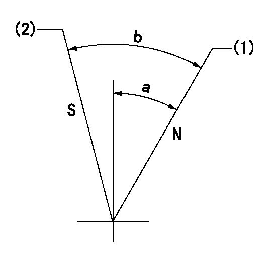
Speed control lever angle

N:Pump normal
S:Stop the pump.
(1)Rack position = aa
(2)Rack position bb
----------
aa=20mm bb=1mm
----------
a=27deg+-5deg b=37deg+-5deg
----------
aa=20mm bb=1mm
----------
a=27deg+-5deg b=37deg+-5deg
0000000901

(1)Pump vertical direction
(2)Position of gear mark 'CC' at No 1 cylinder's beginning of injection
(3)B.T.D.C.: aa
(4)-
----------
aa=9deg
----------
a=(100deg)
----------
aa=9deg
----------
a=(100deg)
Stop lever angle

(PWM) Pulse width modulation (%)
(R) Rack position (mm)
Rack sensor output characteristics
1. Rack limit adjustment
(1)Measure the rack position R2 for PWM a2%.
(2)Confirm that it is within the range R2 = 15+-1 mm.
(3)Measure the rack position R1 at PWM a %.
(4)Confirm that it is within the range R2 - R1 = 10+-0.1 mm.
2. Check the limp home operation.
(1)Move the switch box's limp home switch to the limp home side.
(2)Confirm rack position L1 (mm ) and L2 (mm) for PWM in the above table.
3. Check the pull down operation.
(1)Confirm that the rack position is 19 mm at PWM B%.
(2)In the conditions described in the above table, move the switch box's pull down switch to the pull down side and confirm that the rack position momentarily becomes 1 mm or less.
----------
a1=16.25% a2=72.5% L1=1--mm L2=19++mm A=5 % B=95%
----------
----------
a1=16.25% a2=72.5% L1=1--mm L2=19++mm A=5 % B=95%
----------
Information:
REMOVING CONNECTING ROD BEARING CAP4. Push the piston and connecting rod upward until the piston rings clear the cylinder block. Remove the piston and connecting rod from the cylinder block.
REMOVING PISTON
Do not allow the connecting rods to hit the bottom edge of the cylinder bores or crankshaft journals when removing or installing. Check the lower portion of the bores for burrs or scratches. Use crocus cloth to remove any burrs or scratches from bottom edge of the bores.
5. Keep the connecting rod bearing cap with its respective connecting rod and piston.6. Repeat Steps 2 through 5 for the remaining pistons.Install Pistons
1. Rotate the crankshaft to position bearing journal of the piston to be installed.2. Lubricate the crankshaft bearing journal, bore in cylinder block, piston, rings, and connecting rod bearings with clean engine oil (SAE 30).3. Install a 1Y7426 Ring Compressor (3), or the 4S9450 Compressor (1) and the 4S9446 Clamp (2) from the 4S9458 Teflon Seal Tool Group, on the piston to compress the rings. Install the piston and connecting rod in cylinder bore with piston crater toward vee of engine. Guide the lower end of connecting rod over the crankshaft journal to prevent damage to the crankshaft.
INSTALLING PISTON
1. 4S9450 Compressor. 2. 4S9446 Clamp.
INSTALLING PISTON ALTERNATE METHOD
3. 1Y7426 Ring Compressor.4. Install the connecting rod cap to connecting rod so numbers correspond and both numbers appear on the same side. Lubricate bolt threads, seating faces of cap and nuts, install the retaining nuts and tighten to 30 3 lb. ft. (4.1 0.4 mkg). Mark cap and nut with matching marks. Tighten additional from mark 60° 5°.5. Repeat Steps 1 thru 4 for the remaining pistons.Disassemble Piston
PISTON ASSEMBLY1. Use ring expander (1) to remove rings.
REMOVING RINGS
1. 5F9059 Ring Expander.2. Remove snap ring (5) and push piston pin (2) out of piston (4) and connecting rod (3).
PISTON DISASSEMBLED
2. Piston pin. 3. Connecting rod. 4. Piston. 5. Snap ring.Assemble Piston
1. Install connecting rod into piston with boss on rod on same side as crater in piston crown.
CONNECTING ROD AND PISTON
CONNECTING ROD AND PISTON Installation of connecting rods WITHOUT BOSS on rod; Install connecting rod into piston with cylinder identification number (as marked on the lower end of the rod and on the cap) 180° opposite the crater in piston crown.2. Install piston pin and snap rings.3. Use the 8S2304 Piston Ring Groove Cleaner to clean the piston ring grooves before installing piston rings.4. Install oil ring spring (6) before installing oil ring.
8S2304 RING GROOVE CLEANER
INSTALLING OIL RING SPRING
6. Oil ring spring.5. Use a 5F9059 Ring Expander to install piston rings. Install compression ring with side marked "TOP" toward top of piston. Install oil ring with gap 180° from oil ring spring joint and approximately 120° from compression ring gap.
Have questions with 101402-7631?
Group cross 101402-7631 ZEXEL
Isuzu
101402-7631
INJECTION-PUMP ASSEMBLY
4BG1-T
4BG1-T