Information injection-pump assembly
BOSCH
9 400 611 244
9400611244
ZEXEL
101402-7560
1014027560
ISUZU
8972240310
8972240310
Rating:
Service parts 101402-7560 INJECTION-PUMP ASSEMBLY:
1.
_
5.
AUTOM. ADVANCE MECHANIS
6.
COUPLING PLATE
8.
_
9.
_
11.
Nozzle and Holder
1-15300-291-2
12.
Open Pre:MPa(Kqf/cm2)
18.1{185}

15.
NOZZLE SET
Cross reference number
BOSCH
9 400 611 244
9400611244
ZEXEL
101402-7560
1014027560
ISUZU
8972240310
8972240310
Zexel num
Bosch num
Firm num
Name
101402-7560
9 400 611 244
8972240310 ISUZU
INJECTION-PUMP ASSEMBLY
4BG1 K 14BC INJECTION PUMP ASSY PE4A,5A, PE
4BG1 K 14BC INJECTION PUMP ASSY PE4A,5A, PE
Calibration Data:
Adjustment conditions
Test oil
1404 Test oil ISO4113 or {SAEJ967d}
1404 Test oil ISO4113 or {SAEJ967d}
Test oil temperature
degC
40
40
45
Nozzle and nozzle holder
105780-8140
Bosch type code
EF8511/9A
Nozzle
105780-0000
Bosch type code
DN12SD12T
Nozzle holder
105780-2080
Bosch type code
EF8511/9
Opening pressure
MPa
17.2
Opening pressure
kgf/cm2
175
Injection pipe
Outer diameter - inner diameter - length (mm) mm 6-2-600
Outer diameter - inner diameter - length (mm) mm 6-2-600
Overflow valve
131424-4920
Overflow valve opening pressure
kPa
127
107
147
Overflow valve opening pressure
kgf/cm2
1.3
1.1
1.5
Tester oil delivery pressure
kPa
157
157
157
Tester oil delivery pressure
kgf/cm2
1.6
1.6
1.6
Direction of rotation (viewed from drive side)
Right R
Right R
Injection timing adjustment
Direction of rotation (viewed from drive side)
Right R
Right R
Injection order
1-3-4-2
Pre-stroke
mm
3.6
3.55
3.65
Beginning of injection position
Drive side NO.1
Drive side NO.1
Difference between angles 1
Cal 1-3 deg. 90 89.5 90.5
Cal 1-3 deg. 90 89.5 90.5
Difference between angles 2
Cal 1-4 deg. 180 179.5 180.5
Cal 1-4 deg. 180 179.5 180.5
Difference between angles 3
Cyl.1-2 deg. 270 269.5 270.5
Cyl.1-2 deg. 270 269.5 270.5
Injection quantity adjustment
Adjusting point
A
Rack position
10.5
Pump speed
r/min
875
875
875
Average injection quantity
mm3/st.
70.5
69.4
71.6
Max. variation between cylinders
%
0
-2
2
Basic
*
Fixing the lever
*
Injection quantity adjustment_02
Adjusting point
-
Rack position
8.8+-0.5
Pump speed
r/min
500
500
500
Average injection quantity
mm3/st.
15.5
14.1
16.9
Max. variation between cylinders
%
0
-14
14
Fixing the rack
*
Remarks
Adjust only variation between cylinders; adjust governor according to governor specifications.
Adjust only variation between cylinders; adjust governor according to governor specifications.
Injection quantity adjustment_03
Adjusting point
C
Rack position
-
Pump speed
r/min
100
100
100
Average injection quantity
mm3/st.
125
120
130
Fixing the lever
*
Rack limit
*
Test data Ex:
Governor adjustment
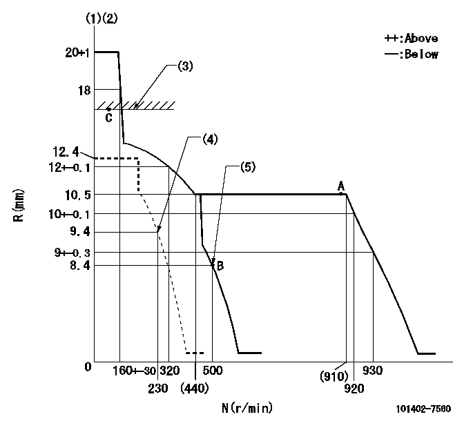
N:Pump speed
R:Rack position (mm)
(1)Target notch: K
(2)Tolerance for racks not indicated: +-0.05mm.
(3)RACK LIMIT
(4)Set idle sub-spring
(5)Main spring setting
----------
K=8
----------
----------
K=8
----------
Speed control lever angle

F:Full speed
I:Idle
(1)Stopper bolt setting
----------
----------
a=13deg+-5deg b=0deg+-5deg
----------
----------
a=13deg+-5deg b=0deg+-5deg
Stop lever angle
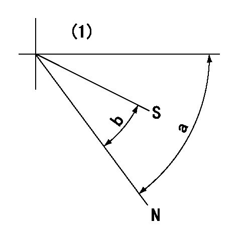
N:Pump normal
S:Stop the pump.
(1)No return spring
----------
----------
a=66.5deg+-5deg b=53deg+-5deg
----------
----------
a=66.5deg+-5deg b=53deg+-5deg
Timing setting

(1)Pump vertical direction
(2)Position of gear mark 'CC' at No 1 cylinder's beginning of injection
(3)B.T.D.C.: aa
(4)-
----------
aa=13deg
----------
a=(100deg)
----------
aa=13deg
----------
a=(100deg)
Information:
TIMING SLOT PLUG (Typical Example)
1. Plug.2. Rotate the engine crankshaft CLOCKWISE (as viewed from front of engine) until the timing pin drops into the timing slot in the fuel pump camshaft.3. Remove retaining screw (2) and washer (3) from end of engine camshaft.4. Remove automatic timing advance unit (4) from the camshaft.
REMOVING TIMING ADVANCE RETAINING SCREW
2. Retaining screw. 3. Washer. 4. Automatic timing advance unit.Install Automatic Timing Advance Unit
1. If timing mark on crankshaft gear and timing mark on camshaft gear are not aligned, rotate the crankshaft CLOCKWISE (as viewed from front of engine) until timing mark on crankshaft gear is aligned with timing mark on camshaft gear.
TIMING MARKS2. Align holes in weights with dowels in gear and install the automatic timing advance unit.3. Align pin (5) in washer with hole (6) in camshaft and install washer (3).
INSTALLING WASHER
3. Washer. 5. Pin. 6. Hole.4. Install retaining screw (2) and tighten to 108 36 lb. in. (124.5 41.5 cm.kg). Stake screw in two places.
STAKING SCREW (Typical Example)
2. Retaining screw.
Stake retaining screw (2) carefully. Heavy blows on washer or retaining screw can force the shaft extension too far into the camshaft and eliminate all end clearance.
5. After retaining screw (2) is staked, the gear and weight assembly requires .003 to .027 in. (0.08 to 0.69 mm) end clearance to prevent binding against the washer, camshaft end, or camshaft gear.
Have questions with 101402-7560?
Group cross 101402-7560 ZEXEL
Isuzu
101402-7560
9 400 611 244
8972240310
INJECTION-PUMP ASSEMBLY
4BG1
4BG1