Information injection-pump assembly
BOSCH
9 400 613 971
9400613971
ZEXEL
101402-7460
1014027460
ISUZU
8972177850
8972177850
Rating:
Service parts 101402-7460 INJECTION-PUMP ASSEMBLY:
1.
_
5.
AUTOM. ADVANCE MECHANIS
6.
COUPLING PLATE
8.
_
9.
_
10.
NOZZLE AND HOLDER ASSY
11.
Nozzle and Holder
12.
Open Pre:MPa(Kqf/cm2)
13.
NOZZLE-HOLDER
14.
NOZZLE
15.
NOZZLE SET
Cross reference number
BOSCH
9 400 613 971
9400613971
ZEXEL
101402-7460
1014027460
ISUZU
8972177850
8972177850
Zexel num
Bosch num
Firm num
Name
101402-7460
9 400 613 971
8972177850 ISUZU
INJECTION-PUMP ASSEMBLY
4BG1-T K 14BC INJECTION PUMP ASSY PE4A,5A, PE
4BG1-T K 14BC INJECTION PUMP ASSY PE4A,5A, PE
Calibration Data:
Adjustment conditions
Test oil
1404 Test oil ISO4113 or {SAEJ967d}
1404 Test oil ISO4113 or {SAEJ967d}
Test oil temperature
degC
40
40
45
Nozzle and nozzle holder
105780-8140
Bosch type code
EF8511/9A
Nozzle
105780-0000
Bosch type code
DN12SD12T
Nozzle holder
105780-2080
Bosch type code
EF8511/9
Opening pressure
MPa
17.2
Opening pressure
kgf/cm2
175
Injection pipe
Outer diameter - inner diameter - length (mm) mm 6-2-600
Outer diameter - inner diameter - length (mm) mm 6-2-600
Overflow valve
131424-4920
Overflow valve opening pressure
kPa
127
107
147
Overflow valve opening pressure
kgf/cm2
1.3
1.1
1.5
Tester oil delivery pressure
kPa
157
157
157
Tester oil delivery pressure
kgf/cm2
1.6
1.6
1.6
Direction of rotation (viewed from drive side)
Right R
Right R
Injection timing adjustment
Direction of rotation (viewed from drive side)
Right R
Right R
Injection order
1-3-4-2
Pre-stroke
mm
3.4
3.35
3.45
Beginning of injection position
Drive side NO.1
Drive side NO.1
Difference between angles 1
Cal 1-3 deg. 90 89.5 90.5
Cal 1-3 deg. 90 89.5 90.5
Difference between angles 2
Cal 1-4 deg. 180 179.5 180.5
Cal 1-4 deg. 180 179.5 180.5
Difference between angles 3
Cyl.1-2 deg. 270 269.5 270.5
Cyl.1-2 deg. 270 269.5 270.5
Injection quantity adjustment
Adjusting point
A
Rack position
9.4
Pump speed
r/min
900
900
900
Average injection quantity
mm3/st.
75
73.9
76.1
Max. variation between cylinders
%
0
-2
2
Basic
*
Fixing the rack
*
Injection quantity adjustment_02
Adjusting point
-
Rack position
7.2+-0.5
Pump speed
r/min
500
500
500
Average injection quantity
mm3/st.
8.8
7.4
10.2
Max. variation between cylinders
%
0
-14
14
Fixing the rack
*
Remarks
Adjust only variation between cylinders; adjust governor according to governor specifications.
Adjust only variation between cylinders; adjust governor according to governor specifications.
Injection quantity adjustment_03
Adjusting point
D
Rack position
-
Pump speed
r/min
100
100
100
Average injection quantity
mm3/st.
90
85
95
Fixing the lever
*
Rack limit
*
Test data Ex:
Governor adjustment
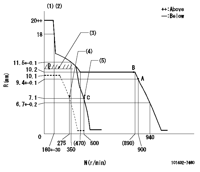
N:Pump speed
R:Rack position (mm)
(1)Target notch: K
(2)Tolerance for racks not indicated: +-0.05mm.
(3)RACK LIMIT
(4)Set idle sub-spring
(5)Main spring setting
----------
K=14
----------
----------
K=14
----------
Speed control lever angle

F:Full speed
I:Idle
(1)Stopper bolt setting
----------
----------
a=(5deg)+-5deg b=(16deg)+-5deg
----------
----------
a=(5deg)+-5deg b=(16deg)+-5deg
Stop lever angle

N:Pump normal
S:Stop the pump.
(1)Normal
----------
----------
a=4.5deg+-5deg b=53deg+-5deg
----------
----------
a=4.5deg+-5deg b=53deg+-5deg
Timing setting

(1)Pump vertical direction
(2)Position of gear mark 'CC' at No 1 cylinder's beginning of injection
(3)B.T.D.C.: aa
(4)-
----------
aa=12deg
----------
a=(100deg)
----------
aa=12deg
----------
a=(100deg)
Information:
BLACK OR GRAY Engine Runs Smooth Recommended Procedure1. Engine Used at an Altitude Higher Than 2500 ft. (762 m) At altitudes higher than 2500 ft. (762 m) the rack setting must be changed on 1145, 1150, and 1160 Engines to keep the smoke at a correct level. See the RACK SETTING INFORMATION for the correct rack setting.2. Engine Used in a Lug Condition "Lugging" (when the truck is used in a gear too high for engine rpm to go up as accelerator pedal is pushed farther down, or when the truck is used in a gear where engine rpm goes down with accelerator pedal at maximum travel) the engine causes a reduction in the intake of air with full fuel delivery to the cylinders. Because there is not enough air to burn all the fuel, the fuel that is not used comes out the exhaust as black smoke. To prevent lugging the engine, use a gear where engine can have "acceleration" (increase in speed) under load.3. Dirty Air Cleaner If the air cleaner has a restriction indicator, see if the red piston is in view. If there is no restriction indicator, restriction can be checked with a water manometer or a vacuum gauge (which measures in inches of water). Make the connection to the engine side of the air cleaner or to the engine inlet manifold. Check with the engine running at full load rpm. Maximum restriction is 25 in. (635 mm) of water. If a gauge is not available, visually check the air cleaner element for dirt. If the element is dirty, clean the element or install a new element.4. Air Inlet Piping Damage or Restriction Make a visual inspection of the air inlet system and check for damage to piping, rags in the inlet piping, or damage to the rain cap or the cap pushed too far on the inlet pipe. If no damage is seen, check inlet restriction with a clean air cleaner element.5. Exhaust System Restriction Make a visual inspection of the exhaust system. Check for damage to piping or for a bad muffler. If no damage is found, check the system by removing the exhaust pipes from the exhaust manifolds. With the exhaust pipes removed, start and run the engine to see if the problem is corrected.6. Fuel Injection Timing Not Correct Check and make necessary adjustments as per Testing and Adjusting section of the Service Manual.7. Rack Setting Too High Check and make necessary adjustments as per Testing and Adjusting section of the Service Manual. See the RACK SETTING INFORMATION for the correct rack setting.8. Low Quality Fuel Test the engine with fuel according to recommendations by the Caterpillar Tractor Co.9. Valve Adjustment Not Correct or Valve Leakage Check and make necessary adjustments as per Testing and Adjusting section of the Service Manual. Intake valve adjustment is .015 in. (0,38 mm) and exhaust valve adjustment is .025 in. (0,64 mm). Valve leakage normally causes the engine to "misfire" (ignition not regular)
Have questions with 101402-7460?
Group cross 101402-7460 ZEXEL
Isuzu
101402-7460
9 400 613 971
8972177850
INJECTION-PUMP ASSEMBLY
4BG1-T
4BG1-T