Information injection-pump assembly
BOSCH
9 400 619 833
9400619833
ZEXEL
101402-7360
1014027360
ISUZU
8972063870
8972063870
Rating:
Service parts 101402-7360 INJECTION-PUMP ASSEMBLY:
1.
_
5.
AUTOM. ADVANCE MECHANIS
6.
COUPLING PLATE
8.
_
9.
_
11.
Nozzle and Holder
12.
Open Pre:MPa(Kqf/cm2)
22.1
15.
NOZZLE SET
Cross reference number
BOSCH
9 400 619 833
9400619833
ZEXEL
101402-7360
1014027360
ISUZU
8972063870
8972063870
Zexel num
Bosch num
Firm num
Name
Calibration Data:
Adjustment conditions
Test oil
1404 Test oil ISO4113 or {SAEJ967d}
1404 Test oil ISO4113 or {SAEJ967d}
Test oil temperature
degC
40
40
45
Nozzle and nozzle holder
105780-8140
Bosch type code
EF8511/9A
Nozzle
105780-0000
Bosch type code
DN12SD12T
Nozzle holder
105780-2080
Bosch type code
EF8511/9
Opening pressure
MPa
17.2
Opening pressure
kgf/cm2
175
Injection pipe
Outer diameter - inner diameter - length (mm) mm 6-2-600
Outer diameter - inner diameter - length (mm) mm 6-2-600
Overflow valve
131424-4920
Overflow valve opening pressure
kPa
127
107
147
Overflow valve opening pressure
kgf/cm2
1.3
1.1
1.5
Tester oil delivery pressure
kPa
157
157
157
Tester oil delivery pressure
kgf/cm2
1.6
1.6
1.6
Direction of rotation (viewed from drive side)
Right R
Right R
Injection timing adjustment
Direction of rotation (viewed from drive side)
Right R
Right R
Injection order
1-3-4-2
Pre-stroke
mm
3.6
3.55
3.65
Beginning of injection position
Drive side NO.1
Drive side NO.1
Difference between angles 1
Cal 1-3 deg. 90 89.5 90.5
Cal 1-3 deg. 90 89.5 90.5
Difference between angles 2
Cal 1-4 deg. 180 179.5 180.5
Cal 1-4 deg. 180 179.5 180.5
Difference between angles 3
Cyl.1-2 deg. 270 269.5 270.5
Cyl.1-2 deg. 270 269.5 270.5
Injection quantity adjustment
Adjusting point
A
Rack position
8.6
Pump speed
r/min
1400
1400
1400
Average injection quantity
mm3/st.
104
102.4
105.6
Max. variation between cylinders
%
0
-2.5
2.5
Basic
*
Fixing the lever
*
Injection quantity adjustment_02
Adjusting point
C
Rack position
6+-0.5
Pump speed
r/min
275
275
275
Average injection quantity
mm3/st.
15
13.7
16.3
Max. variation between cylinders
%
0
-14
14
Fixing the rack
*
Test data Ex:
Governor adjustment
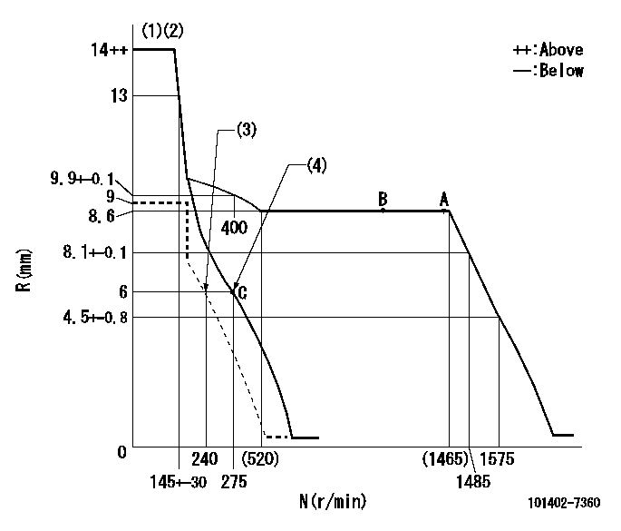
N:Pump speed
R:Rack position (mm)
(1)Target notch: K
(2)Tolerance for racks not indicated: +-0.05mm.
(3)Set idle sub-spring
(4)Main spring setting
----------
K=14
----------
----------
K=14
----------
Speed control lever angle

F:Full speed
I:Idle
(1)Stopper bolt setting
----------
----------
a=(15deg)+-5deg b=(28deg)+-5deg
----------
----------
a=(15deg)+-5deg b=(28deg)+-5deg
Stop lever angle

N:Pump normal
S:Stop the pump.
----------
----------
a=19deg+-5deg b=53deg+-5deg
----------
----------
a=19deg+-5deg b=53deg+-5deg
Timing setting

(1)Pump vertical direction
(2)Position of gear mark 'CC' at No 1 cylinder's beginning of injection
(3)B.T.D.C.: aa
(4)-
----------
aa=20deg
----------
a=(90deg)
----------
aa=20deg
----------
a=(90deg)
Information:
Cooling system components identified are: 1-Fan mounting and drive. 2-Water temperature regulator and housing. 3-Water pump.Water Temperature Regulator
1-Seal. Install seal with lip toward top of cover. 2-Washer.Fan Drive
5F7465 Pullertwo 3/8" NC bolts4 in. (101,6 mm) longand flat washers.
Tools required to remove pulley (1): 5F7465 Puller, two 3/8" NC bolts, 4 in. (101,6 mm) long, and flat washers. Refer to the GENERAL INSTRUCTIONS.Water Pump Disassembly And Assembly
Refer to SERVICE GUIDE for Preliminary Information.8B7548 Push Puller8H663 Bearing Pulling Attachment8B7560 Step Plate8H684 Ratchet Box Wrench1/2" NC Forcing Screw. 1 Install seal assembly in the following manner: a. Wet the outside diameter of the rubber cup-ceramic ring assembly, and the pump housing seal bore, with water. Using hand pressure only, install the rubber seat and ceramic seat squarely in the pump housing bore.b. Wet the inside diameter of the rubber bellows-carbon washer assembly and the water pump shaft with water. Using hand pressure only, install the rubber bellows-carbon washer assembly on the water pump shaft until carbon washer contacts the ceramic ring.c. Install the spring, then install the impeller.2, 4, 5 Remove bearings and gear using an 8B7548 Push Puller, 8H663 Bearing Pulling Attachment, 8B7560 Step Plate, 8H684 Ratchet Box Wrench. Refer to the GENERAL INSTRUCTIONS. Heat bearings and gear to 300° F. (149° C.) before installing on water pump shaft. Do not install shaft in pump housing until gear and bearings have cooled to room temperature.3 Use a 1/2" NC forcing screw to remove impeller. Install the impeller by pressing it onto the water pump shaft until it bottoms on the pump shaft shoulder.