Information injection-pump assembly
BOSCH
9 400 610 488
9400610488
ZEXEL
101402-7220
1014027220
ISUZU
8971769960
8971769960

Rating:
Service parts 101402-7220 INJECTION-PUMP ASSEMBLY:
1.
_

5.
AUTOM. ADVANCE MECHANIS
6.
COUPLING PLATE
8.
_
9.
_
11.
Nozzle and Holder
1-15300-331-0
12.
Open Pre:MPa(Kqf/cm2)
18.1{185}

15.
NOZZLE SET
Cross reference number
BOSCH
9 400 610 488
9400610488
ZEXEL
101402-7220
1014027220
ISUZU
8971769960
8971769960
Zexel num
Bosch num
Firm num
Name
101402-7220
9 400 610 488
8971769960 ISUZU
INJECTION-PUMP ASSEMBLY
4BG1-T K 14BC INJECTION PUMP ASSY PE4A,5A, PE
4BG1-T K 14BC INJECTION PUMP ASSY PE4A,5A, PE
Calibration Data:
Adjustment conditions
Test oil
1404 Test oil ISO4113 or {SAEJ967d}
1404 Test oil ISO4113 or {SAEJ967d}
Test oil temperature
degC
40
40
45
Nozzle and nozzle holder
105780-8140
Bosch type code
EF8511/9A
Nozzle
105780-0000
Bosch type code
DN12SD12T
Nozzle holder
105780-2080
Bosch type code
EF8511/9
Opening pressure
MPa
17.2
Opening pressure
kgf/cm2
175
Injection pipe
Outer diameter - inner diameter - length (mm) mm 6-2-600
Outer diameter - inner diameter - length (mm) mm 6-2-600
Overflow valve
131424-4920
Overflow valve opening pressure
kPa
127
107
147
Overflow valve opening pressure
kgf/cm2
1.3
1.1
1.5
Tester oil delivery pressure
kPa
157
157
157
Tester oil delivery pressure
kgf/cm2
1.6
1.6
1.6
Direction of rotation (viewed from drive side)
Right R
Right R
Injection timing adjustment
Direction of rotation (viewed from drive side)
Right R
Right R
Injection order
1-3-4-2
Pre-stroke
mm
3.4
3.35
3.45
Beginning of injection position
Drive side NO.1
Drive side NO.1
Difference between angles 1
Cal 1-3 deg. 90 89.5 90.5
Cal 1-3 deg. 90 89.5 90.5
Difference between angles 2
Cal 1-4 deg. 180 179.5 180.5
Cal 1-4 deg. 180 179.5 180.5
Difference between angles 3
Cyl.1-2 deg. 270 269.5 270.5
Cyl.1-2 deg. 270 269.5 270.5
Injection quantity adjustment
Adjusting point
A
Rack position
8.4
Pump speed
r/min
1050
1050
1050
Average injection quantity
mm3/st.
84.5
83.4
85.6
Max. variation between cylinders
%
0
-2
2
Basic
*
Fixing the lever
*
Injection quantity adjustment_02
Adjusting point
C
Rack position
6.1+-0.5
Pump speed
r/min
350
350
350
Average injection quantity
mm3/st.
8.5
7.1
9.9
Max. variation between cylinders
%
0
-14
14
Fixing the rack
*
Injection quantity adjustment_03
Adjusting point
D
Rack position
-
Pump speed
r/min
100
100
100
Average injection quantity
mm3/st.
135
130
140
Fixing the lever
*
Rack limit
*
Test data Ex:
Governor adjustment
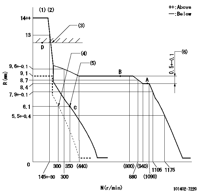
N:Pump speed
R:Rack position (mm)
(1)Target notch: K
(2)Tolerance for racks not indicated: +-0.05mm.
(3)RACK LIMIT
(4)Set idle sub-spring
(5)Main spring setting
(6)Rack difference between N = N1 and N = N2
----------
K=8 N1=1050r/min N2=700r/min
----------
----------
K=8 N1=1050r/min N2=700r/min
----------
Speed control lever angle

F:Full speed
I:Idle
(1)Stopper bolt setting
----------
----------
a=4deg+-5deg b=22deg+-5deg
----------
----------
a=4deg+-5deg b=22deg+-5deg
Stop lever angle

N:Pump normal
S:Stop the pump.
----------
----------
a=4.5deg+-5deg b=53deg+-5deg
----------
----------
a=4.5deg+-5deg b=53deg+-5deg
Timing setting

(1)Pump vertical direction
(2)Position of gear mark 'CC' at No 1 cylinder's beginning of injection
(3)B.T.D.C.: aa
(4)-
----------
aa=12deg
----------
a=(100deg)
----------
aa=12deg
----------
a=(100deg)
Information:
start by: a) remove oil pump1. Check the connecting rods and caps for their identification and location.2. Turn crankshaft until connecting rod caps are in position shown. 3. Remove the nuts (1) and the cap from connecting rod. Remove lower half of bearing from cap.4. Push the connecting rod away from the crankshaft. Remove the upper half of bearing from connecting rod. Install the bearings dry when the clearance checks are made. Put clean engine oil on the bearings for final assembly.5. Install upper half of bearing in connecting rod.6. Pull the connecting rod slowly on to the crankshaft.7. Install lower half of bearing in cap. Be sure the tabs in back of bearings are in the tab grooves of connecting rod and cap.
Do not use an impact wrench to tighten the bolts the additional 120° 5°.
8. Use Plastigage (A) to check bearing clearance.9. Put Plastigage (A) on the bearing.10. Put clean engine oil on threads of rod bolts and seat surfaces of nuts. Be sure the cylinder numbers on the rod cap and rod are the same and are on the same side of the connecting rod. Numbers are on the same side of rod and caps as are the grooves for the bearing tabs. If new rods are installed, put the cylinder number on the rod and cap. Do not turn the crankshaft when Plastigage (A) is in position. 11. Install the rod caps (2). Install the nuts. Tighten each nut to a torque of 60 6 lb. ft. (80 8 N m). Put a mark on the nuts and cap and tighten nuts an extra 120° 5° from the mark. Remove the rod cap. Remove Plastigage (A) and check the bearing clearance. The bearing clearance must be .0028 to .0066 in. (0.071 to 0.168 mm) for new bearings. Maximum clearance with used bearings is .010 in. (0.25 mm).12. Put clean engine oil on lower half of bearing. Install rod cap again. Tighten each nut to 60 6 lb.ft. (80 8 N m). Put a mark on nuts and cap and tighten nuts an extra 120° 5° from mark.13. Do Steps 1 through 12 for remainder of connecting rod bearings.end by:a) install oil pump
Have questions with 101402-7220?
Group cross 101402-7220 ZEXEL
Isuzu
101402-7220
9 400 610 488
8971769960
INJECTION-PUMP ASSEMBLY
4BG1-T
4BG1-T