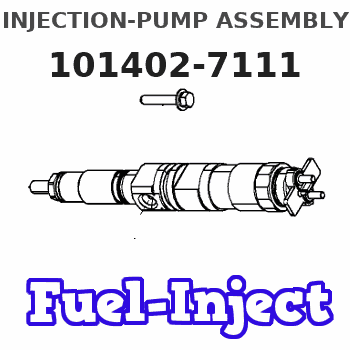
Information injection-pump assembly
BOSCH
9 400 613 951
9400613951
ZEXEL
101402-7111
1014027111
ISUZU
8971697550
8971697550
Rating:
Service parts 101402-7111 INJECTION-PUMP ASSEMBLY:
1.
_

5.
AUTOM. ADVANCE MECHANIS
6.
COUPLING PLATE
8.
_
9.
_
11.
Nozzle and Holder
12.
Open Pre:MPa(Kqf/cm2)
18.1{185}

15.
NOZZLE SET
Include in #1:
101402-7111
as INJECTION-PUMP ASSEMBLY
Include in #2:
104206-1032
as _
Cross reference number
BOSCH
9 400 613 951
9400613951
ZEXEL
101402-7111
1014027111
ISUZU
8971697550
8971697550
Zexel num
Bosch num
Firm num
Name
101402-7111
9 400 613 951
8971697550 ISUZU
INJECTION-PUMP ASSEMBLY
4BG1-T K 14BC INJECTION PUMP ASSY PE4A,5A, PE
4BG1-T K 14BC INJECTION PUMP ASSY PE4A,5A, PE
Calibration Data:
Adjustment conditions
Test oil
1404 Test oil ISO4113 or {SAEJ967d}
1404 Test oil ISO4113 or {SAEJ967d}
Test oil temperature
degC
40
40
45
Nozzle and nozzle holder
105780-8140
Bosch type code
EF8511/9A
Nozzle
105780-0000
Bosch type code
DN12SD12T
Nozzle holder
105780-2080
Bosch type code
EF8511/9
Opening pressure
MPa
17.2
Opening pressure
kgf/cm2
175
Injection pipe
Outer diameter - inner diameter - length (mm) mm 6-2-600
Outer diameter - inner diameter - length (mm) mm 6-2-600
Overflow valve
131424-4920
Overflow valve opening pressure
kPa
127
107
147
Overflow valve opening pressure
kgf/cm2
1.3
1.1
1.5
Tester oil delivery pressure
kPa
157
157
157
Tester oil delivery pressure
kgf/cm2
1.6
1.6
1.6
Direction of rotation (viewed from drive side)
Right R
Right R
Injection timing adjustment
Direction of rotation (viewed from drive side)
Right R
Right R
Injection order
1-3-4-2
Pre-stroke
mm
3.2
3.15
3.25
Beginning of injection position
Drive side NO.1
Drive side NO.1
Difference between angles 1
Cal 1-3 deg. 90 89.5 90.5
Cal 1-3 deg. 90 89.5 90.5
Difference between angles 2
Cal 1-4 deg. 180 179.5 180.5
Cal 1-4 deg. 180 179.5 180.5
Difference between angles 3
Cyl.1-2 deg. 270 269.5 270.5
Cyl.1-2 deg. 270 269.5 270.5
Injection quantity adjustment
Adjusting point
A
Rack position
9.1
Pump speed
r/min
1200
1200
1200
Average injection quantity
mm3/st.
100.5
99.4
101.6
Max. variation between cylinders
%
0
-2
2
Basic
*
Fixing the lever
*
Injection quantity adjustment_02
Adjusting point
-
Rack position
6.1+-0.5
Pump speed
r/min
435
435
435
Average injection quantity
mm3/st.
8.5
7.1
9.9
Max. variation between cylinders
%
0
-14
14
Fixing the rack
*
Remarks
Adjust only variation between cylinders; adjust governor according to governor specifications.
Adjust only variation between cylinders; adjust governor according to governor specifications.
Test data Ex:
Governor adjustment
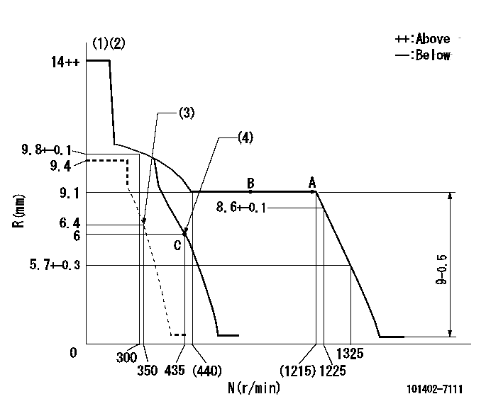
N:Pump speed
R:Rack position (mm)
(1)Target notch: K
(2)Tolerance for racks not indicated: +-0.05mm.
(3)Set idle sub-spring
(4)Main spring setting
----------
K=6
----------
----------
K=6
----------
Speed control lever angle
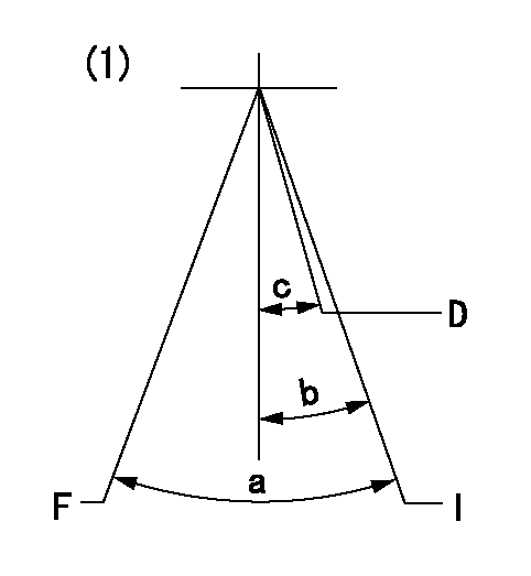
F:Full speed
I:Idle
D:Dead point
(1)With variable lever
----------
----------
a=(26deg)+-5deg b=(22deg)+-5deg c=(13deg)+-3deg
----------
----------
a=(26deg)+-5deg b=(22deg)+-5deg c=(13deg)+-3deg
Stop lever angle

N:Pump normal
S:Stop the pump.
(1)Normal
----------
----------
a=6deg+-5deg b=46deg+-5deg
----------
----------
a=6deg+-5deg b=46deg+-5deg
Timing setting

(1)Pump vertical direction
(2)Position of gear mark 'CC' at No 1 cylinder's beginning of injection
(3)B.T.D.C.: aa
(4)-
----------
aa=12deg
----------
a=(100deg)
----------
aa=12deg
----------
a=(100deg)
Information:
start by:a) separation of governor from fuel injection pump housing 1. Remove the protection caps and felt washers (1) from pumps.2. Use wrench (A) to remove bushings (2) that hold the fuel injection pumps into the housing. Remove seals (3).3. Use extractor (B) to remove the pumps from the pump housing. Put identification on the injection pumps as to their location in the pump housing.4. Remove bonnet (4), ring (5), spring (6) and check valve (7) from barrel (8).5. Remove plunger assembly (11), washer (10) and spring (9) from the barrel.
Be careful not to cause damage to plunger assemblies. Keep the same cylinder pump and plunger together, the plunger from one pump can not be installed in another group.
6. Remove rack (12) from the housing. 7. Remove spacers (13) and lifters (14) from the housing. Keep the spacers and lifters together with identification as to their location in the pump housing. 8. Remove two bolts (16), lock and two sleeves from the gear assembly.9. Remove gear assembly (15) from the camshaft. 10. Remove two bolts, plate (17) and the spacer that hold the camshaft in position in the pump housing. 11. Remove the camshaft from the pump housing. 12. Use tool group (C) to remove the camshaft bearings from the pump housing.13. Remove the bearings for the fuel rack from the pump housing.Assemble Fuel Injection Pump Housing
1. Use tooling (C) to install the camshaft bearings in the fuel injection pump housing. Install the camshaft bearing joints 15° from the vertical centerline of the bores. Install the front and rear camshaft bearings even with the fuel injection pump housing. Install the center camshaft bearing a distance of 4.81 .02 in. (122.2 0.5 mm) from the rear face of the fuel injection pump housing. 2. Use tooling (F) to install the bearing with a tab for the groove in the rack.3. Use tooling (E) to install the rear bearing for the rack. Install the bearing to a depth of .282 .005 in. (7.16 0.13 mm). The small holes in the rear bearing must be installed parallel to the vertical centerline of the pump. 4. Put clean engine oil on the camshaft. Install the camshaft in the pump housing. 5. Install the spacer, plate (1) and two bolts that hold the camshaft in place in the pump housing. 6. Put gear assembly (2) in position on the end of the camshaft. Be sure rod (3) is in the groove of the camshaft. 7. Install sleeves (4), lock and two bolts on the gear assembly. 8. Install spacers (5) with their respective lifters (6) in the pump housing. If new lifters and/or pumps are to be installed, make adjustment of the fuel pump timing dimension. See SETTING THE INJECTION PUMP TIMING DIMENSION: OFF ENGINE TESTING AND ADJUSTING. 9. Install rack (7) in the pump housing.10. Assemble the fuel injection pumps as follows: a) Put clean fuel on all parts.b) Install the spring, washers and plunger in the
Have questions with 101402-7111?
Group cross 101402-7111 ZEXEL
Isuzu
Isuzu
Isuzu
101402-7111
9 400 613 951
8971697550
INJECTION-PUMP ASSEMBLY
4BG1-T
4BG1-T