Information injection-pump assembly
BOSCH
9 400 613 911
9400613911
ZEXEL
101402-4330
1014024330
ISUZU
8971073700
8971073700

Rating:
Service parts 101402-4330 INJECTION-PUMP ASSEMBLY:
1.
_

5.
AUTOM. ADVANCE MECHANIS
6.
COUPLING PLATE
8.
_
9.
_
11.
Nozzle and Holder
8-97016-146-1
12.
Open Pre:MPa(Kqf/cm2)
18.1{185}

15.
NOZZLE SET
Cross reference number
BOSCH
9 400 613 911
9400613911
ZEXEL
101402-4330
1014024330
ISUZU
8971073700
8971073700
Zexel num
Bosch num
Firm num
Name
9 400 613 911
8971073700 ISUZU
INJECTION-PUMP ASSEMBLY
4BD1PTA * K 14BC PE4A,5A, PE
4BD1PTA * K 14BC PE4A,5A, PE
Calibration Data:
Adjustment conditions
Test oil
1404 Test oil ISO4113 or {SAEJ967d}
1404 Test oil ISO4113 or {SAEJ967d}
Test oil temperature
degC
40
40
45
Nozzle and nozzle holder
105780-8140
Bosch type code
EF8511/9A
Nozzle
105780-0000
Bosch type code
DN12SD12T
Nozzle holder
105780-2080
Bosch type code
EF8511/9
Opening pressure
MPa
17.2
Opening pressure
kgf/cm2
175
Injection pipe
Outer diameter - inner diameter - length (mm) mm 6-2-600
Outer diameter - inner diameter - length (mm) mm 6-2-600
Tester oil delivery pressure
kPa
157
157
157
Tester oil delivery pressure
kgf/cm2
1.6
1.6
1.6
Direction of rotation (viewed from drive side)
Right R
Right R
Injection timing adjustment
Direction of rotation (viewed from drive side)
Right R
Right R
Injection order
1-3-4-2
Pre-stroke
mm
3.4
3.35
3.45
Beginning of injection position
Drive side NO.1
Drive side NO.1
Difference between angles 1
Cal 1-3 deg. 90 89.5 90.5
Cal 1-3 deg. 90 89.5 90.5
Difference between angles 2
Cal 1-4 deg. 180 179.5 180.5
Cal 1-4 deg. 180 179.5 180.5
Difference between angles 3
Cyl.1-2 deg. 270 269.5 270.5
Cyl.1-2 deg. 270 269.5 270.5
Injection quantity adjustment
Adjusting point
A
Rack position
10.1
Pump speed
r/min
1150
1150
1150
Average injection quantity
mm3/st.
83.5
82
85
Max. variation between cylinders
%
0
-2
2
Basic
*
Fixing the lever
*
Injection quantity adjustment_02
Adjusting point
B
Rack position
6.5+-0.5
Pump speed
r/min
400
400
400
Average injection quantity
mm3/st.
8
6.6
9.4
Max. variation between cylinders
%
0
-14
14
Fixing the rack
*
Test data Ex:
Governor adjustment
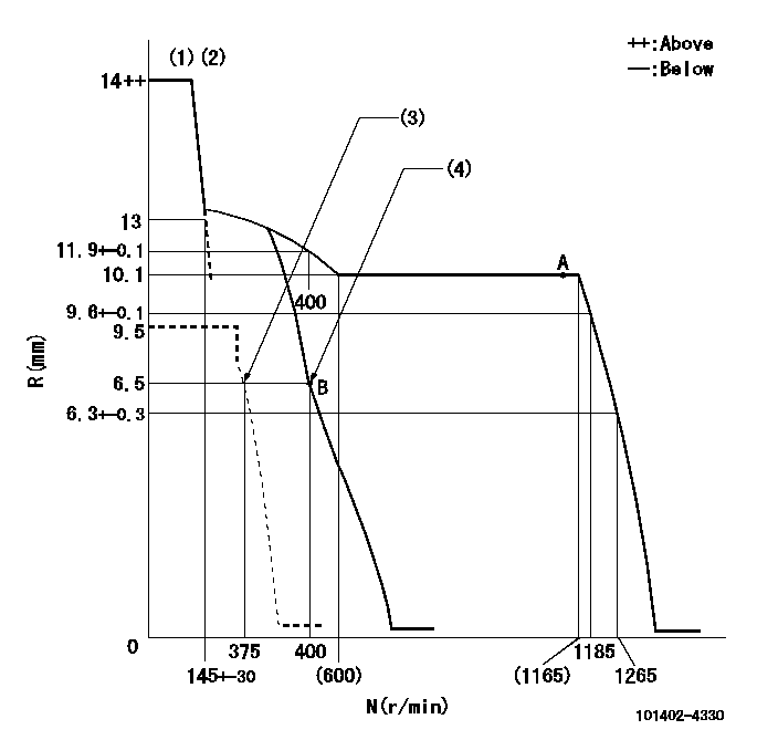
N:Pump speed
R:Rack position (mm)
(1)Target notch: K
(2)Tolerance for racks not indicated: +-0.05mm.
(3)Set idle sub-spring
(4)Main spring setting
----------
K=5
----------
----------
K=5
----------
Speed control lever angle
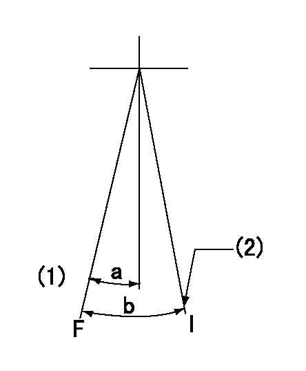
F:Full speed
I:Idle
(1)-
(2)Stopper bolt setting
----------
----------
a=4deg+-5deg b=23deg+-5deg
----------
----------
a=4deg+-5deg b=23deg+-5deg
Stop lever angle

N:Pump normal
S:Stop the pump.
----------
----------
a=19deg+-5deg b=53deg+-5deg
----------
----------
a=19deg+-5deg b=53deg+-5deg
Timing setting

(1)Pump vertical direction
(2)Position of gear mark 'CC' at No 1 cylinder's beginning of injection
(3)B.T.D.C.: aa
(4)-
----------
aa=18deg
----------
a=(90deg)
----------
aa=18deg
----------
a=(90deg)
Information:
b. Operate vehicle at 60% of rated speed with moderate load until oil and coolant temperatures reach their normal range for operation. If there is a heavy vibration, drive shaft whip, tire bounce, etc., do not continue with dynamometer test until cause of the problem is corrected. Engines that have had new internal parts installed should be operated on a run-in schedule before operation at full load. For run-in schedule information, make reference to General Instructions section of this Service Manual.2. Put transmission in direct gear and the differential in the highest speed ratio. Operate vehicle at maximum engine speed and increase chassis dynamometer load until a speed of 50 rpm less than rated speed is reached (continuity light should be on). Maintain this speed for one minute and record the engine speed and wheel horsepower. If horsepower is low and poor maintenance is suspected, remove air cleaner or inlet piping to turbocharger and check horsepower again to see if a plugged air cleaner could be the problem.3a. If the wheel horsepower is correct, find the balance point of the engine (speed at which the load stop pin just touches the torque spring or stop bar). At this point the continuity light should flicker (go off and on dimly). If the balance point is correct, then the low power complaint can not be validated. No further test or repairs are necessary.If the balance point is low, see Procedure No. 5.3b. If the wheel horsepower is below the correct value, find the balance point of the engine (speed at which the load stop pin just touches the torque spring or stop bar). At this point the continuity light should flicker (go off and on dimly). If the balance point is correct, see Procedure No. 6.If the balance point is low, see Procedure No. 4.4. Stop the engine. Remove the AFRC (air-fuel ratio control). Put a cover over the hole where the AFRC was installed. Start the engine and check the balance point and horsepower again. If both of these are now correct, the problem is in AFRC. Repair or replace the AFRC. If, with the AFRC removed, horsepower is now acceptable and balance point is low, the problem is still with AFRC. Repair or replace the AFRC. Then adjust balance point according to Procedure No. 5.5. If the balance point is low, the high idle will have to be increased to raise the balance point to the correct rpm (the point at which the continuity light just comes on). If the balance point is still low and high idle has been adjusted to maximum, disengage clutch while maximum throttle position is maintained. Now observe high idle rpm and, if lower than previously adjusted, check frame-to-engine-mount. A damaged or loose engine mount may put the linkage in a bind and thus prevent maximum governor position at load conditions.6. If the balance point was correct and the wheel horsepower was low, install the 4S6553 Engine Test Group and do the wheel