Information injection-pump assembly
BOSCH
9 400 613 908
9400613908
ZEXEL
101402-4300
1014024300
ISUZU
8971045020
8971045020
Rating:
Service parts 101402-4300 INJECTION-PUMP ASSEMBLY:
1.
_
5.
AUTOM. ADVANCE MECHANIS
6.
COUPLING PLATE
8.
_
9.
_
11.
Nozzle and Holder
8-97020-033-1
12.
Open Pre:MPa(Kqf/cm2)
22.1{225}
15.
NOZZLE SET
Cross reference number
BOSCH
9 400 613 908
9400613908
ZEXEL
101402-4300
1014024300
ISUZU
8971045020
8971045020
Zexel num
Bosch num
Firm num
Name
101402-4300
9 400 613 908
8971045020 ISUZU
INJECTION-PUMP ASSEMBLY
4BG1 K 14BD INJECTION PUMP ASSY PE4AD PE
4BG1 K 14BD INJECTION PUMP ASSY PE4AD PE
Calibration Data:
Adjustment conditions
Test oil
1404 Test oil ISO4113 or {SAEJ967d}
1404 Test oil ISO4113 or {SAEJ967d}
Test oil temperature
degC
40
40
45
Nozzle and nozzle holder
105780-8140
Bosch type code
EF8511/9A
Nozzle
105780-0000
Bosch type code
DN12SD12T
Nozzle holder
105780-2080
Bosch type code
EF8511/9
Opening pressure
MPa
17.2
Opening pressure
kgf/cm2
175
Injection pipe
Outer diameter - inner diameter - length (mm) mm 6-2-600
Outer diameter - inner diameter - length (mm) mm 6-2-600
Overflow valve
131424-4920
Overflow valve opening pressure
kPa
127
107
147
Overflow valve opening pressure
kgf/cm2
1.3
1.1
1.5
Tester oil delivery pressure
kPa
157
157
157
Tester oil delivery pressure
kgf/cm2
1.6
1.6
1.6
Direction of rotation (viewed from drive side)
Right R
Right R
Injection timing adjustment
Direction of rotation (viewed from drive side)
Right R
Right R
Injection order
1-3-4-2
Pre-stroke
mm
3.6
3.55
3.65
Beginning of injection position
Drive side NO.1
Drive side NO.1
Difference between angles 1
Cal 1-3 deg. 90 89.5 90.5
Cal 1-3 deg. 90 89.5 90.5
Difference between angles 2
Cal 1-4 deg. 180 179.5 180.5
Cal 1-4 deg. 180 179.5 180.5
Difference between angles 3
Cyl.1-2 deg. 270 269.5 270.5
Cyl.1-2 deg. 270 269.5 270.5
Injection quantity adjustment
Adjusting point
A
Rack position
9.9
Pump speed
r/min
1400
1400
1400
Average injection quantity
mm3/st.
139
137.4
140.6
Max. variation between cylinders
%
0
-2.5
2.5
Basic
*
Fixing the lever
*
Boost pressure
kPa
97.3
97.3
Boost pressure
mmHg
730
730
Injection quantity adjustment_02
Adjusting point
B
Rack position
5.9+-0.5
Pump speed
r/min
275
275
275
Average injection quantity
mm3/st.
15.5
14.2
16.8
Max. variation between cylinders
%
0
-14
14
Fixing the rack
*
Boost pressure
kPa
0
0
0
Boost pressure
mmHg
0
0
0
Boost compensator adjustment
Pump speed
r/min
550
550
550
Rack position
8.3
Boost pressure
kPa
33.3
30.6
36
Boost pressure
mmHg
250
230
270
Boost compensator adjustment_02
Pump speed
r/min
550
550
550
Rack position
9
Boost pressure
kPa
53.3
49.3
57.3
Boost pressure
mmHg
400
370
430
Boost compensator adjustment_03
Pump speed
r/min
550
550
550
Rack position
(9.9)
Boost pressure
kPa
84
84
84
Boost pressure
mmHg
630
630
630
Test data Ex:
Governor adjustment
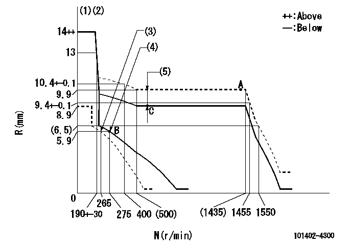
N:Pump speed
R:Rack position (mm)
(1)Notch fixed: K
(2)Tolerance for racks not indicated: +-0.05mm.
(3)Set idle sub-spring
(4)Main spring setting
(5)Boost compensator stroke: BCL
----------
K=20 BCL=(1.6)+-0.1mm
----------
----------
K=20 BCL=(1.6)+-0.1mm
----------
Speed control lever angle
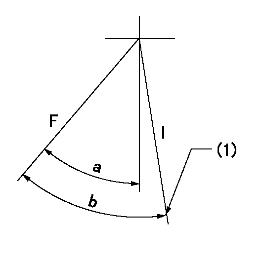
F:Full speed
I:Idle
(1)Stopper bolt setting
----------
----------
a=(21deg)+-5deg b=(26deg)+-5deg
----------
----------
a=(21deg)+-5deg b=(26deg)+-5deg
Stop lever angle
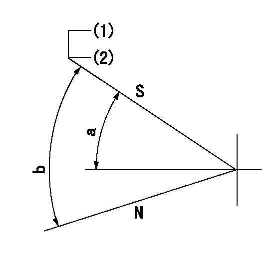
N:Pump normal
S:Stop the pump.
(1)Pump speed aa and rack position bb (to be sealed at delivery)
(2)Stopper bolt setting
----------
----------
a=32deg+-5deg b=(55deg)
----------
----------
a=32deg+-5deg b=(55deg)
Timing setting
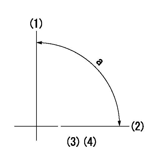
(1)Pump vertical direction
(2)Position of gear mark 'CC' at No 1 cylinder's beginning of injection
(3)B.T.D.C.: aa
(4)-
----------
aa=12deg
----------
a=(90deg)
----------
aa=12deg
----------
a=(90deg)
Information:
Crankshaft
The crankshaft changes the combustion forces in the cylinders into usable rotating torque which powers the machine. There is a timing gear at each end of the crankshaft which drives the respective timing gears.The bearing surfaces on the crankshaft get oil for lubrication through passages drilled in the crankshaft.Vibration Damper
The twisting of the crankshaft, due to the regular power impacts along its length, is called twisting (torsional) vibration. The vibration damper is installed on the front end of the crankshaft. It is used for reduction of torsional vibrations and stops the vibration from building up to amounts that cause damage.
CROSS SECTION OF A TYPICAL RUBBER VIBRATION DAMPER
1. Flywheel ring. 2. Rubber ring. 3. Inner hub.The rubber damper is made of a flywheel ring (1) connected to an inner hub (3) by a rubber ring (2). The rubber makes a flexible coupling between the flywheel ring and the inner hub.The viscous damper is made of a weight (1) in a metal case (3). The small space (2) between the case and weight is filled with a thick fluid. The fluid permits the weight to move in the case to cause a reduction of vibrations of the crankshaft.
CROSS SECTION OF A TYPICAL VISCOUS VIBRATION DAMPER
1. Solid cast iron weight. 2. Space between weight and case. 3. Case.Electrical System
The electrical system has three separate circuits: the charging circuit, the starting circuit and the low amperage circuit. Some of the electrical system components are in more than one circuit. The battery (batteries), circuit breaker, ammeter, cables and wires from the battery are all common in each of the circuits.
The disconnect switch must be in the ON position to let the electrical system operate. There will be damage to some of the charging circuit components if the engine is running with the disconnect switch in the OFF position.
The charging circuit is in operation when the engine is running. An alternator makes electricity for the charging circuit. A voltage regulator in the circuit controls the electrical output to keep the battery at full charge.The starting circuit is in operation only when the disconnect switch is put in the ON position and the start switch is activated.The starting circuit has a glow plug for each cylinder of the diesel engine. Glow plugs are small heating units in the precombustion chambers. Glow plugs give aid for ignition of the fuel when the engine is started in temperatures that are low.The low amperage load circuit and the charging circuit are both connected to the same side of the ammeter. The starting circuit connects to the opposite side of the ammeter.Charging System Components
Alternator (Prestolite) 2P1204
2P1204 ALTERNATORThe alternator is driven by two V type belts from the fan pulley. It is a 24 volt, 19 ampere unit with a regulator which has no moving parts (solid state) installed on the side opposite the pulley. The alternator is made up of the following parts: head assembly on the drive end, rotor assembly, stator assembly, rectifier and heat removal assemblies, brush
Have questions with 101402-4300?
Group cross 101402-4300 ZEXEL
Isuzu
101402-4300
9 400 613 908
8971045020
INJECTION-PUMP ASSEMBLY
4BG1
4BG1