Information injection-pump assembly
ZEXEL
101402-4201
1014024201
ISUZU
8970486851
8970486851
Rating:
Service parts 101402-4201 INJECTION-PUMP ASSEMBLY:
1.
_
5.
AUTOM. ADVANCE MECHANIS
6.
COUPLING PLATE
8.
_
9.
_
11.
Nozzle and Holder
8-94447-686-1
12.
Open Pre:MPa(Kqf/cm2)
21.6{220}
15.
NOZZLE SET
Cross reference number
ZEXEL
101402-4201
1014024201
ISUZU
8970486851
8970486851
Zexel num
Bosch num
Firm num
Name
Calibration Data:
Adjustment conditions
Test oil
1404 Test oil ISO4113 or {SAEJ967d}
1404 Test oil ISO4113 or {SAEJ967d}
Test oil temperature
degC
40
40
45
Nozzle and nozzle holder
105780-8140
Bosch type code
EF8511/9A
Nozzle
105780-0000
Bosch type code
DN12SD12T
Nozzle holder
105780-2080
Bosch type code
EF8511/9
Opening pressure
MPa
17.2
Opening pressure
kgf/cm2
175
Injection pipe
Outer diameter - inner diameter - length (mm) mm 6-2-600
Outer diameter - inner diameter - length (mm) mm 6-2-600
Overflow valve
131424-4920
Overflow valve opening pressure
kPa
127
107
147
Overflow valve opening pressure
kgf/cm2
1.3
1.1
1.5
Tester oil delivery pressure
kPa
157
157
157
Tester oil delivery pressure
kgf/cm2
1.6
1.6
1.6
Direction of rotation (viewed from drive side)
Right R
Right R
Injection timing adjustment
Direction of rotation (viewed from drive side)
Right R
Right R
Injection order
1-3-4-2
Pre-stroke
mm
3.4
3.35
3.45
Beginning of injection position
Drive side NO.1
Drive side NO.1
Difference between angles 1
Cal 1-3 deg. 90 89.5 90.5
Cal 1-3 deg. 90 89.5 90.5
Difference between angles 2
Cal 1-4 deg. 180 179.5 180.5
Cal 1-4 deg. 180 179.5 180.5
Difference between angles 3
Cyl.1-2 deg. 270 269.5 270.5
Cyl.1-2 deg. 270 269.5 270.5
Injection quantity adjustment
Adjusting point
A
Rack position
9.7
Pump speed
r/min
1150
1150
1150
Average injection quantity
mm3/st.
77.6
76.5
78.7
Max. variation between cylinders
%
0
-2
2
Basic
*
Fixing the lever
*
Injection quantity adjustment_02
Adjusting point
-
Rack position
6.6+-0.5
Pump speed
r/min
475
475
475
Average injection quantity
mm3/st.
8.8
7.4
10.2
Max. variation between cylinders
%
0
-14
14
Fixing the rack
*
Remarks
Adjust only variation between cylinders; adjust governor according to governor specifications.
Adjust only variation between cylinders; adjust governor according to governor specifications.
Test data Ex:
Governor adjustment
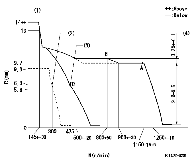
N:Pump speed
R:Rack position (mm)
(1)Target notch: K
(2)Set idle sub-spring
(3)Main spring setting
(4)Rack difference between N = N1 and N = N2
----------
K=6 N1=1150r/min N2=800r/min
----------
----------
K=6 N1=1150r/min N2=800r/min
----------
Speed control lever angle
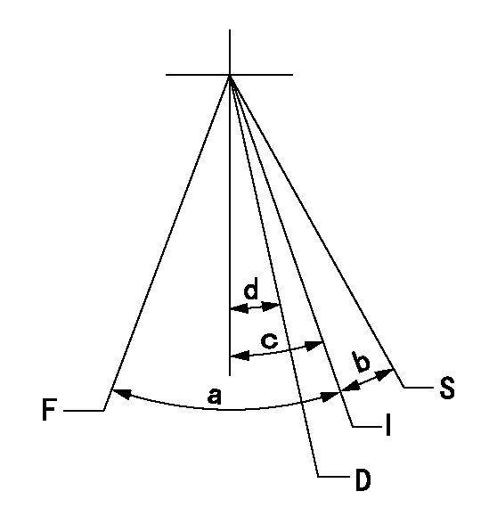
F:Full speed
I:Idle
D:Dead point
S:Stop
----------
----------
a=(20deg)+-5deg b=(16deg)+-5deg c=(18deg)+-5deg d=13deg+-3deg
----------
----------
a=(20deg)+-5deg b=(16deg)+-5deg c=(18deg)+-5deg d=13deg+-3deg
Stop lever angle
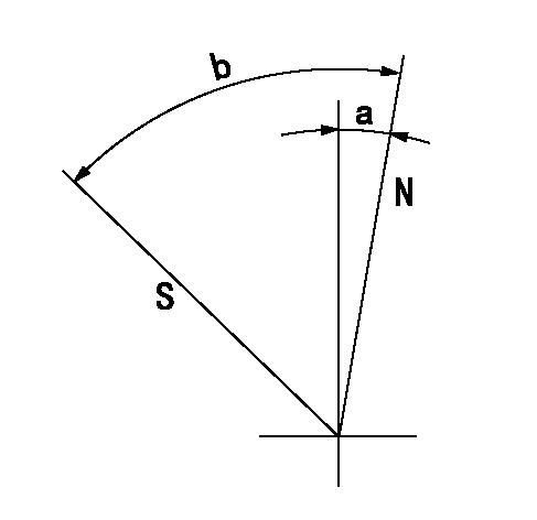
N:Pump normal
S:Stop the pump.
----------
----------
a=6deg+-5deg b=46deg+-5deg
----------
----------
a=6deg+-5deg b=46deg+-5deg
0000001501 LEVER
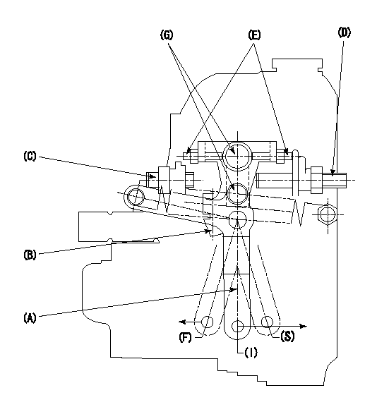
1. Variable lever adjustment
(1)Fix lever B in the idle position using the bolts C and D.
(2)Temporarily fix lever A in center of long hole.
(3)Set the dead point position temporarily and measure the lever angle.
(4)After idle adjustment, loosen the full side stopper bolt D.
(5)Move lever A in full speed direction.
(6)Fix the bolt D at the full speed position.
(7)Fix lever A using bolt E.
(8)(G) Lock using bolt.
(9)Finally, measure the lever angle and set the idle stopper bolt (C) stop position.
----------
----------
----------
----------
Timing setting
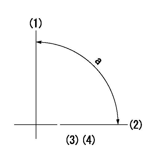
(1)Pump vertical direction
(2)Position of gear mark 'CC' at No 1 cylinder's beginning of injection
(3)B.T.D.C.: aa
(4)-
----------
aa=18deg
----------
a=(90deg)
----------
aa=18deg
----------
a=(90deg)
Information:
2. Remove oil filter base support (2), air line (3) and oil level gauge tube (4). Remove the right lifting eye (1) and the left lifting eye. 3. Remove glow plug leads (5) and the 3/8 in. bolts from the cylinder head. Glow plug leads are on the precombustion engine only.4. Install two 5/16"-18 NC forged eyebolts and nuts in the cylinder head. Fasten a hoist to the cylinder head.5. Remove cylinder head bolts (6) and the washers. Clean all debris or foreign material from the "V" of the engine before removal of the cylinder head.6. Remove the cylinder head. Weight of the cylinder head is 200 lb. (90 kg). Put a cover over the intake manifold portion of the cylinder head to keep dirt and foreign material out.
Do not put the cylinder head down on a flat surface. This can cause damage to the fuel injection valves.
A new spacer plate gasket must be installed when the cylinder head is removed. See REMOVE AND INSTALL SPACER PLATE.Install Cylinder Head
1. Clean the spacer plate and the bottom surface of the cylinder head. Put a new cylinder head gasket (3) and seals (4) in position on the spacer plate as shown.2. Fasten a hoist to cylinder head (2) and put it in position over dowels (5) in the cylinder block.3. Put clean SAE 30 oil on the threads of the bolts that hold the cylinder head in position. Install the bolts and washers and tighten them to the correct torque as follows: a) Tighten bolts 1 through 14 in number sequence to a torque of 200 20 lb.ft. (270 25 N m).b) Tighten bolts 1 through 14 in number sequence to a torque of 330 15 lb.ft. (447 20 N m).c) Tighten bolts 1 through 14 again in number sequence to a torque of 330 15 lb.ft. (447 20 N m).d) Install the rocker shaft assembly and push rods.e) Tighten bolts 15 through 18 in number sequence to a torque of 200 20 lb.ft. (270 25 N m).f) Tighten bolts 15 through 18 in number sequence to a torque of 330 15 lb.ft. (447 20 N m).g) Tighten bolts 15 through 18 again in number sequence to a torque of 330 15 lb.ft. (447 20 N m).4. Install the glow plug leads and the 3/8 in. bolts in the cylinder head. Tighten the bolts to a torque of 32 5 lb.ft. (43 7 N m). If studs (1) were removed, install new studs and tighten them to a torque of 20 3 lb.ft. (25 4 N m).5. Make an adjustment for the valve clearance. The clearance must be .015 .003 in. (0.38 0.07 mm) for intake and .030 .003 in. (0.76 0.07 mm) for exhaust. See VALVE CLEARANCE SETTING in TESTING AND ADJUSTING.6. Install the left and right lifting eyes.7. Install the oil level gauge tube, air line and oil