Information injection-pump assembly
BOSCH
9 400 613 897
9400613897
ZEXEL
101402-4181
1014024181
ISUZU
8970461831
8970461831
Rating:
Service parts 101402-4181 INJECTION-PUMP ASSEMBLY:
1.
_
5.
AUTOM. ADVANCE MECHANIS
6.
COUPLING PLATE
8.
_
9.
_
11.
Nozzle and Holder
5-15300-103-2
12.
Open Pre:MPa(Kqf/cm2)
14.7{150}
15.
NOZZLE SET
Cross reference number
BOSCH
9 400 613 897
9400613897
ZEXEL
101402-4181
1014024181
ISUZU
8970461831
8970461831
Zexel num
Bosch num
Firm num
Name
9 400 613 897
8970461831 ISUZU
INJECTION-PUMP ASSEMBLY
4BD1 K 14BC INJECTION PUMP ASSY PE4A,5A, PE
4BD1 K 14BC INJECTION PUMP ASSY PE4A,5A, PE
Calibration Data:
Adjustment conditions
Test oil
1404 Test oil ISO4113 or {SAEJ967d}
1404 Test oil ISO4113 or {SAEJ967d}
Test oil temperature
degC
40
40
45
Nozzle and nozzle holder
105780-8140
Bosch type code
EF8511/9A
Nozzle
105780-0000
Bosch type code
DN12SD12T
Nozzle holder
105780-2080
Bosch type code
EF8511/9
Opening pressure
MPa
17.2
Opening pressure
kgf/cm2
175
Injection pipe
Outer diameter - inner diameter - length (mm) mm 6-2-600
Outer diameter - inner diameter - length (mm) mm 6-2-600
Overflow valve
131424-4920
Overflow valve opening pressure
kPa
127
107
147
Overflow valve opening pressure
kgf/cm2
1.3
1.1
1.5
Tester oil delivery pressure
kPa
157
157
157
Tester oil delivery pressure
kgf/cm2
1.6
1.6
1.6
Direction of rotation (viewed from drive side)
Right R
Right R
Injection timing adjustment
Direction of rotation (viewed from drive side)
Right R
Right R
Injection order
1-3-4-2
Pre-stroke
mm
3.6
3.55
3.65
Beginning of injection position
Drive side NO.1
Drive side NO.1
Difference between angles 1
Cal 1-3 deg. 90 89.5 90.5
Cal 1-3 deg. 90 89.5 90.5
Difference between angles 2
Cal 1-4 deg. 180 179.5 180.5
Cal 1-4 deg. 180 179.5 180.5
Difference between angles 3
Cyl.1-2 deg. 270 269.5 270.5
Cyl.1-2 deg. 270 269.5 270.5
Injection quantity adjustment
Adjusting point
A
Rack position
8.5
Pump speed
r/min
750
750
750
Average injection quantity
mm3/st.
44.2
43.1
45.3
Max. variation between cylinders
%
0
-2
2
Basic
*
Fixing the rack
*
Injection quantity adjustment_02
Adjusting point
-
Rack position
7.4+-0.5
Pump speed
r/min
500
500
500
Average injection quantity
mm3/st.
12.5
11.1
13.9
Max. variation between cylinders
%
0
-14
14
Fixing the rack
*
Remarks
Adjust only variation between cylinders; adjust governor according to governor specifications.
Adjust only variation between cylinders; adjust governor according to governor specifications.
Test data Ex:
Governor adjustment
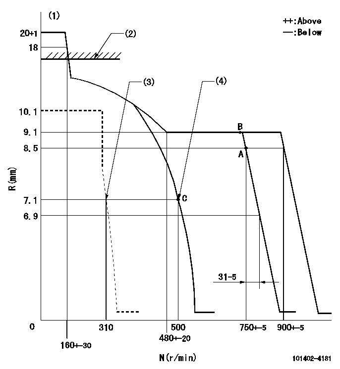
N:Pump speed
R:Rack position (mm)
(1)Target notch: K
(2)RACK CAP: R1
(3)Set idle sub-spring
(4)Main spring setting
----------
K=13 R1=(17.5)mm
----------
----------
K=13 R1=(17.5)mm
----------
Speed control lever angle
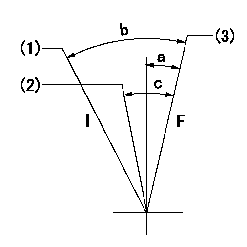
F:Full speed
I:Idle
(1)Stopper bolt setting
(2)Set the pump speed at aa
(3)Set the pump speed at bb (at delivery)
----------
aa=750r/min bb=900r/min
----------
a=4deg+-5deg b=12deg+-5deg c=5deg+-5deg
----------
aa=750r/min bb=900r/min
----------
a=4deg+-5deg b=12deg+-5deg c=5deg+-5deg
Stop lever angle
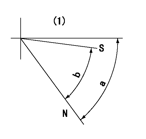
N:Pump normal
S:Stop the pump.
(1)Without return spring
----------
----------
a=66.5deg+-5deg b=53deg+-5deg
----------
----------
a=66.5deg+-5deg b=53deg+-5deg
Timing setting
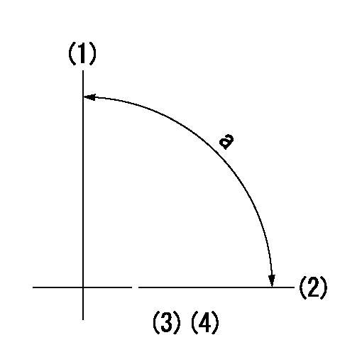
(1)Pump vertical direction
(2)Position of gear mark 'CC' at No 1 cylinder's beginning of injection
(3)B.T.D.C.: aa
(4)-
----------
aa=18deg
----------
a=(90deg)
----------
aa=18deg
----------
a=(90deg)
Information:
start by:a) remove valve covers
Do not let the tops of the fuel nozzles turn when the fuel lines are loosened. The nozzles will be damaged if the top of the nozzles turn in the body.
1. Use tooling (A) to loosen fuel injection line nut (1) at the fuel injection nozzles. 2. Disconnect fuel injection line nut (2) from head adapter nut (3).3. Remove adapter nut (3) and the O-ring seal.4. Move adapter (4) out of the valve cover base, and remove fuel injection line (1). 5. If necessary, remove seal (5) from fuel injection line (1). 6. Remove bolt (7) that holds clamp (6). Clamp (6) cannot be removed until fuel injection nozzle (8) is lifted 25.0 mm (1.00 in.).7. Remove fuel injection nozzle (8) with tooling (B) as follows: a. Install 6V6983 Adapter and 6V4152 Screw (9) [part of tooling (B)] into fuel injection nozzle (8). b. Install 6V6982 Tube Assembly (11) over the 6V4152 Screw. Use 2S5658 Washer and 1B2406 Nut (10) on the 6V4152 Screw to pull fuel injection nozzle (8) from the adapter. Items (10) and (11) are part of tooling (B).
A replacement of compression seal washer (13) and of carbon dam seal (12) must be made each time the fuel injection nozzle is removed. Be sure that the replacement compression seal washer (13) is the same color code and part number as the original compression seal washer. If the wrong thickness washer is used, engine damage could occur. See the Specifications section of this book for more information.
8. Remove carbon dam seal (12) and compression seal washer (13) from fuel injection nozzle (8).Install Fuel Injection Nozzles
1. Use tool (D) to clean adapter bore (1) for the fuel injection nozzle. Use a tap driver to turn tool (D). 2. Install compression seal washer (3) on fuel injection nozzle (4).3. Use tool (A) to install carbon dam seal (2) on fuel injection nozzle (4). Refer to Special Instruction SEHS7292 for the use of tooling (C). 4. Install fuel injection nozzle (4) and clamp (5) as a unit. Install the bolt through the clamp into the adapter. 5. Install O-ring seal (6) on fuel injection line (7) and put clean diesel fuel on it. 6. Install fuel injection line (7). Move adapter (8) into position in the rocker arm cover base.
Do not let the tops of the fuel nozzles turn when the fuel lines are tightened. The nozzles will be damaged if the top of the nozzles turn in the body.
7. Use tooling (B) to tighten the inner fuel line nuts to a torque of 41 7 N m (30 5 lb.ft.). 8. Put clean diesel fuel oil on O-ring seal (11). Install O-ring seal (11) and nut (10). Tighten nut (10) to a torque of 30 5 N m (22 4 lb.ft.).9. Install nut (9) for the fuel injection line, and tighten the fuel injection line nut to a torque of 41 7 N m (30 5 lb.ft.).end by:a)
