Information injection-pump assembly
ZEXEL
101402-4133
1014024133
ISUZU
8970209293
8970209293
Rating:
Service parts 101402-4133 INJECTION-PUMP ASSEMBLY:
1.
_
5.
AUTOM. ADVANCE MECHANIS
6.
COUPLING PLATE
8.
_
9.
_
11.
Nozzle and Holder
8-97013-319-1
12.
Open Pre:MPa(Kqf/cm2)
18.1{185}

15.
NOZZLE SET
Cross reference number
ZEXEL
101402-4133
1014024133
ISUZU
8970209293
8970209293
Zexel num
Bosch num
Firm num
Name
Calibration Data:
Adjustment conditions
Test oil
1404 Test oil ISO4113 or {SAEJ967d}
1404 Test oil ISO4113 or {SAEJ967d}
Test oil temperature
degC
40
40
45
Nozzle and nozzle holder
105780-8140
Bosch type code
EF8511/9A
Nozzle
105780-0000
Bosch type code
DN12SD12T
Nozzle holder
105780-2080
Bosch type code
EF8511/9
Opening pressure
MPa
17.2
Opening pressure
kgf/cm2
175
Injection pipe
Outer diameter - inner diameter - length (mm) mm 6-2-600
Outer diameter - inner diameter - length (mm) mm 6-2-600
Overflow valve
131424-4920
Overflow valve opening pressure
kPa
127
107
147
Overflow valve opening pressure
kgf/cm2
1.3
1.1
1.5
Tester oil delivery pressure
kPa
157
157
157
Tester oil delivery pressure
kgf/cm2
1.6
1.6
1.6
Direction of rotation (viewed from drive side)
Right R
Right R
Injection timing adjustment
Direction of rotation (viewed from drive side)
Right R
Right R
Injection order
1-3-4-2
Pre-stroke
mm
3.4
3.35
3.45
Beginning of injection position
Drive side NO.1
Drive side NO.1
Difference between angles 1
Cal 1-3 deg. 90 89.5 90.5
Cal 1-3 deg. 90 89.5 90.5
Difference between angles 2
Cal 1-4 deg. 180 179.5 180.5
Cal 1-4 deg. 180 179.5 180.5
Difference between angles 3
Cyl.1-2 deg. 270 269.5 270.5
Cyl.1-2 deg. 270 269.5 270.5
Injection quantity adjustment
Adjusting point
A
Rack position
9.3
Pump speed
r/min
1100
1100
1100
Average injection quantity
mm3/st.
69
67.9
70.1
Max. variation between cylinders
%
0
-2
2
Basic
*
Fixing the lever
*
Injection quantity adjustment_02
Adjusting point
-
Rack position
6.6+-0.5
Pump speed
r/min
475
475
475
Average injection quantity
mm3/st.
8.8
7.4
10.2
Max. variation between cylinders
%
0
-14
14
Fixing the rack
*
Remarks
Adjust only variation between cylinders; adjust governor according to governor specifications.
Adjust only variation between cylinders; adjust governor according to governor specifications.
Test data Ex:
Governor adjustment
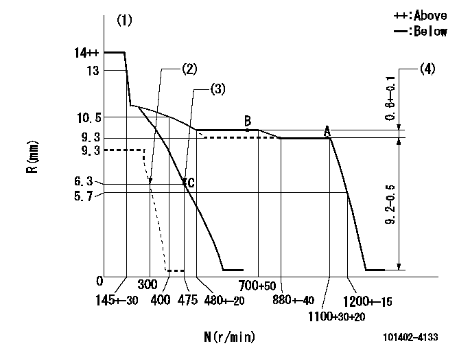
N:Pump speed
R:Rack position (mm)
(1)Target notch: K
(2)Set idle sub-spring
(3)Main spring setting
(4)Rack difference between N = N1 and N = N2
----------
K=6 N1=1100r/min N2=700r/min
----------
----------
K=6 N1=1100r/min N2=700r/min
----------
Speed control lever angle
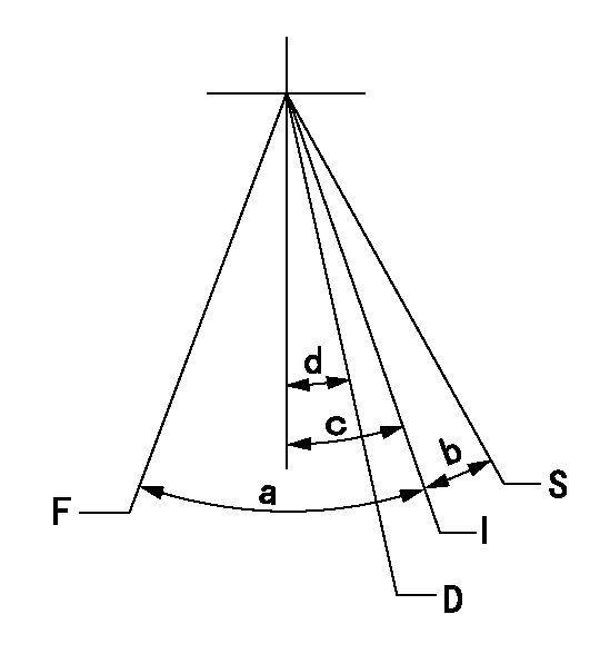
F:Full speed
I:Idle
D:Dead point
S:Stop
----------
----------
a=(19deg)+-5deg b=(15deg)+-5deg c=(17deg)+-5deg d=13deg+-3deg
----------
----------
a=(19deg)+-5deg b=(15deg)+-5deg c=(17deg)+-5deg d=13deg+-3deg
Stop lever angle
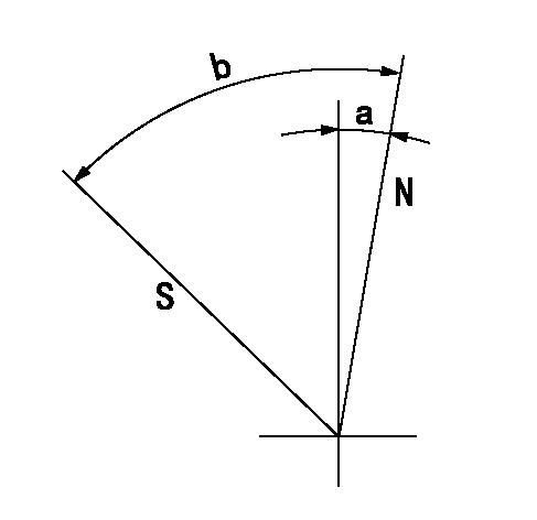
N:Pump normal
S:Stop the pump.
----------
----------
a=6deg+-5deg b=46deg+-5deg
----------
----------
a=6deg+-5deg b=46deg+-5deg
0000001501 LEVER
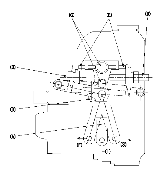
1. Variable lever adjustment
(1)Fix lever B in the idle position using the bolts C and D.
(2)Temporarily fix lever A in center of long hole.
(3)Set the dead point position temporarily and measure the lever angle.
(4)After idle adjustment, loosen the full side stopper bolt D.
(5)Move lever A in full speed direction.
(6)Fix the bolt D at the full speed position.
(7)Fix lever A using bolt E.
(8)(G) Lock using bolt.
(9)Finally, measure the lever angle and set the idle stopper bolt (C) stop position.
----------
----------
----------
----------
Timing setting

(1)Pump vertical direction
(2)Position of gear mark 'CC' at No 1 cylinder's beginning of injection
(3)B.T.D.C.: aa
(4)-
----------
aa=18deg
----------
a=(90deg)
----------
aa=18deg
----------
a=(90deg)
Information:
start by:a) remove fuel ratio controlb) remove shut off solenoid 1. Put a mark of identification on the shaft and lever (1) for correct location at assembly. Loosen the bolt and remove lever (1) from the shaft. 2. Remove the bolts, cover (3) and the gasket.3. Remove the bolt, high idle housing (2) and the gasket. 4. Remove the bolt and housing (4) from the governor. 5. Remove bolt (6) from the stop collar.6. Remove stop collar (5) and the spring from the shaft. 7. Remove the plug from the fuel injection pump housing and install tool (A) with square end (flat end) down. Move the governor control to the "FUEL ON" position until the right rack stops against the timing pin. The racks are now in the center (zero) position. 8. Remove bolts (8) that hold the governor housing to the fuel injection pump housing.9. Remove governor housing (7). 10. Disconnect lines (10) and (11) at the governor control plate.11. Remove the bolts, governor control plate (9) and gasket.
Cover the fuel injection pump housing to keep dirt and all foreign material out of the pump housing.
The drive assembly must be removed from the governor control plate before the control plate can be installed. 12. Remove retainer ring (12) from the drive assembly. 13. Remove dowel (14) and drive assembly (13) from the governor control plate.Install Governor (Later)
Make sure there is no dirt or foreign material in the pump housing.
1. Put gasket (2) in position and install governor control plate (1) and the bolts. 2. Put governor drive (3) in position. Make an alignment of the groove (slot) in the bottom end of the governor drive with the notch in the end of the drive pinion assembly.3. Align the marks on the top of drive (3), stop (4) and the gear. 4. Install dowel (5) in the hole in the gear and stop (4). 5. Install retainer ring (6) on the gear. 6. Put the gasket and governor housing (7) in position on the plate. Install the bolts.7. Connect two lines (8) to the plate. 8. Put spring (11) and collar (9) in position on the shaft. Make an alignment of screw (10) and the groove in the shaft. Tighten screw (10).9. Check the fuel rack setting at this time. See FUEL RACK SETTING in TESTING AND ADJUSTING. 10. If nut (13) was loosened it must be tightened at this time. Tighten nut (13) to a torque of 9 3 lb.ft. (12 4 N m).11. Put the gasket and cover (12) in position. Make sure lever (14) is in position under the collar. Install the bolt that holds cover (12) to the housing. 12. Put the gasket and cover (16) in position and install the bolt.13. Install the gasket, plate (15) and the bolts. 14. Make an alignment of the mark on the shaft with mark on lever (17) and install the lever. Tighten the bolt.
If the lever and the shaft are not in correct alignment,