Information injection-pump assembly
BOSCH
9 400 613 891
9400613891
ZEXEL
101402-4110
1014024110
ISUZU
8943879120
8943879120
Rating:
Service parts 101402-4110 INJECTION-PUMP ASSEMBLY:
1.
_

5.
AUTOM. ADVANCE MECHANIS
6.
COUPLING PLATE
8.
_
9.
_
11.
Nozzle and Holder
5-15300-103-2
12.
Open Pre:MPa(Kqf/cm2)
14.7{150}

15.
NOZZLE SET
Cross reference number
BOSCH
9 400 613 891
9400613891
ZEXEL
101402-4110
1014024110
ISUZU
8943879120
8943879120
Zexel num
Bosch num
Firm num
Name
9 400 613 891
8943879120 ISUZU
INJECTION-PUMP ASSEMBLY
4BD1 K 14BC INJECTION PUMP ASSY PE4A,5A, PE
4BD1 K 14BC INJECTION PUMP ASSY PE4A,5A, PE
Calibration Data:
Adjustment conditions
Test oil
1404 Test oil ISO4113 or {SAEJ967d}
1404 Test oil ISO4113 or {SAEJ967d}
Test oil temperature
degC
40
40
45
Nozzle and nozzle holder
105780-8140
Bosch type code
EF8511/9A
Nozzle
105780-0000
Bosch type code
DN12SD12T
Nozzle holder
105780-2080
Bosch type code
EF8511/9
Opening pressure
MPa
17.2
Opening pressure
kgf/cm2
175
Injection pipe
Outer diameter - inner diameter - length (mm) mm 6-2-600
Outer diameter - inner diameter - length (mm) mm 6-2-600
Overflow valve
131424-4920
Overflow valve opening pressure
kPa
127
107
147
Overflow valve opening pressure
kgf/cm2
1.3
1.1
1.5
Tester oil delivery pressure
kPa
157
157
157
Tester oil delivery pressure
kgf/cm2
1.6
1.6
1.6
Direction of rotation (viewed from drive side)
Right R
Right R
Injection timing adjustment
Direction of rotation (viewed from drive side)
Right R
Right R
Injection order
1-3-4-2
Pre-stroke
mm
3.4
3.35
3.45
Beginning of injection position
Drive side NO.1
Drive side NO.1
Difference between angles 1
Cal 1-3 deg. 90 89.5 90.5
Cal 1-3 deg. 90 89.5 90.5
Difference between angles 2
Cal 1-4 deg. 180 179.5 180.5
Cal 1-4 deg. 180 179.5 180.5
Difference between angles 3
Cyl.1-2 deg. 270 269.5 270.5
Cyl.1-2 deg. 270 269.5 270.5
Injection quantity adjustment
Adjusting point
A
Rack position
7.9
Pump speed
r/min
1200
1200
1200
Average injection quantity
mm3/st.
63.2
62.1
64.3
Max. variation between cylinders
%
0
-2
2
Basic
*
Fixing the lever
*
Injection quantity adjustment_02
Adjusting point
C
Rack position
5.9+-0.5
Pump speed
r/min
350
350
350
Average injection quantity
mm3/st.
8
6.6
9.4
Max. variation between cylinders
%
0
-14
14
Fixing the rack
*
Injection quantity adjustment_03
Adjusting point
D
Rack position
-
Pump speed
r/min
100
100
100
Average injection quantity
mm3/st.
86
86
96
Fixing the lever
*
Rack limit
*
Test data Ex:
Governor adjustment
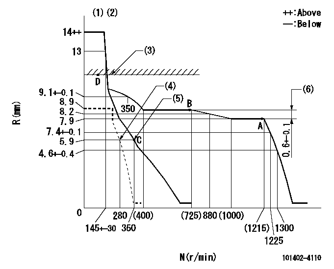
N:Pump speed
R:Rack position (mm)
(1)Target notch: K
(2)Tolerance for racks not indicated: +-0.05mm.
(3)RACK LIMIT
(4)Set idle sub-spring
(5)Main spring setting
(6)Rack difference between N = N1 and N = N2
----------
K=9 N1=1200r/min N2=700r/min
----------
----------
K=9 N1=1200r/min N2=700r/min
----------
Speed control lever angle
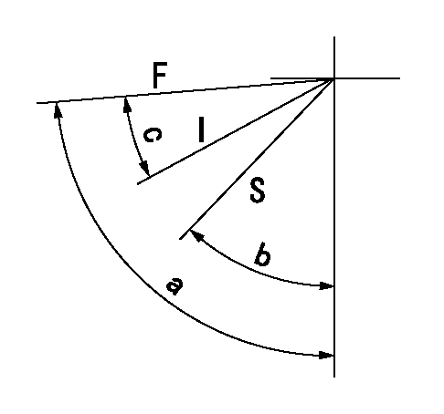
F:Full speed
I:Idle
S:Stop
----------
----------
a=81deg+-5deg b=40deg+-3deg c=22deg+-5deg
----------
----------
a=81deg+-5deg b=40deg+-3deg c=22deg+-5deg
Stop lever angle

N:Pump normal
S:Stop the pump.
(1)Normal
----------
----------
a=19deg+-5deg b=53deg+-5deg
----------
----------
a=19deg+-5deg b=53deg+-5deg
Timing setting

(1)Pump vertical direction
(2)Position of gear mark 'CC' at No 1 cylinder's beginning of injection
(3)B.T.D.C.: aa
(4)-
----------
aa=18deg
----------
a=(90deg)
----------
aa=18deg
----------
a=(90deg)
Information:
start by:a) remove turbocharger1. Put identification marks on the two housings and the cartridge assembly for use at assembly. 2. Remove two clamps (3) and make a separation of compressor housing (1) and turbine housing (2) from the cartridge assembly.
When the nut is loosened, do not put a side force on the shaft.
3. Put cartridge assembly (4) in position on tooling (A). Remove the nut from the shaft. 4. Use a press to push the shaft assembly out of the cartridge assembly. Remove compressor wheel (5). 5. Remove seal ring (8) and shroud (7) from shaft assembly (6). 6. Remove snap ring (9) with tool (B). 7. Use two screwdrivers to remove insert (10) from the cartridge housing. 8. Remove O-ring seal (12) from the insert.9. Remove sleeve (11) from the insert. Remove the seal ring from the sleeve. 10. Remove deflector (13) from the housing. 11. Remove bearing (14) from the cartridge housing. 12. Remove sleeve (15) and bearing (16) from the cartridge housing. 13. Remove ring (17). 14. Use tool (C) to remove snap ring (19), bearing (18) and snap ring (20) from the cartridge housing. 15. Turn the cartridge housing over. Use tool (C) to remove snap ring (22), bearing (21) and snap ring (23) from the housing.Assemble Turbocharger (Schwitzer 4MF)
1. Make sure all oil passages are open and clean. Put clean engine oil on all parts before assembly. 2. Use tool (A) to install snap ring (2), bearing (3) and snap ring (1) in the housing. Install the snap rings with the round side toward the bearing. 3. Turn the housing over. Use tool (A) to install snap ring (5), bearing (6) and snap ring (4). Install the snap rings with the round side toward the bearing. 4. Put ring (7) in position in the housing. 5. Put bearing (8) in position. Make an alignment of the holes in the bearing with the dowels in the housing. Grooved side of the bearing must be up.6. Put sleeve (9) in position in the housing. 7. Put ring (10) in position on top of the bearing. 8. Install deflector (11) as shown. 9. Put seal ring (13) in position on sleeve (12). Install the sleeve in insert (15).10. Put O-ring seal (14) in position on the insert. 11. Put insert assembly (16) in position in the housing. 12. Use tool (B) to install snap ring (17) in the housing. 13. Put shaft assembly (18) in position on tooling (C).14. Put 6V2055 High Vacuum Grease in the seal ring groove on the shaft assembly.15. Install seal ring (19) on shaft assembly (18). 16. Put shroud (20) in position on the shaft assembly.17. Put cartridge housing (22) and compressor wheel (21) in position on the shaft assembly.
Do not put a side force on the shaft when the nut is tightened.
18. Put a small amount of oil on the face of the compressor wheel that will be under the nut. Install the nut and tighten it to a torque