Information injection-pump assembly
ZEXEL
101402-3892
1014023892

Rating:
Service parts 101402-3892 INJECTION-PUMP ASSEMBLY:
1.
_
5.
AUTOM. ADVANCE MECHANIS
6.
COUPLING PLATE
7.
COUPLING PLATE
8.
_
9.
_
10.
NOZZLE AND HOLDER ASSY
11.
Nozzle and Holder
12.
Open Pre:MPa(Kqf/cm2)
21.6{220}
13.
NOZZLE-HOLDER
14.
NOZZLE
15.
NOZZLE SET
Cross reference number
ZEXEL
101402-3892
1014023892
Zexel num
Bosch num
Firm num
Name
101402-3892
INJECTION-PUMP ASSEMBLY
14BC PE4A,5A, PE
14BC PE4A,5A, PE
Calibration Data:
Adjustment conditions
Test oil
1404 Test oil ISO4113 or {SAEJ967d}
1404 Test oil ISO4113 or {SAEJ967d}
Test oil temperature
degC
40
40
45
Nozzle and nozzle holder
105780-8140
Bosch type code
EF8511/9A
Nozzle
105780-0000
Bosch type code
DN12SD12T
Nozzle holder
105780-2080
Bosch type code
EF8511/9
Opening pressure
MPa
17.2
Opening pressure
kgf/cm2
175
Injection pipe
Outer diameter - inner diameter - length (mm) mm 6-2-600
Outer diameter - inner diameter - length (mm) mm 6-2-600
Overflow valve
131424-3420
Overflow valve opening pressure
kPa
255
221
289
Overflow valve opening pressure
kgf/cm2
2.6
2.25
2.95
Tester oil delivery pressure
kPa
157
157
157
Tester oil delivery pressure
kgf/cm2
1.6
1.6
1.6
Direction of rotation (viewed from drive side)
Right R
Right R
Injection timing adjustment
Direction of rotation (viewed from drive side)
Right R
Right R
Injection order
1-3-4-2
Pre-stroke
mm
2.5
2.45
2.55
Beginning of injection position
Drive side NO.1
Drive side NO.1
Difference between angles 1
Cal 1-3 deg. 90 89.5 90.5
Cal 1-3 deg. 90 89.5 90.5
Difference between angles 2
Cal 1-4 deg. 180 179.5 180.5
Cal 1-4 deg. 180 179.5 180.5
Difference between angles 3
Cyl.1-2 deg. 270 269.5 270.5
Cyl.1-2 deg. 270 269.5 270.5
Injection quantity adjustment
Adjusting point
A
Rack position
9.7
Pump speed
r/min
1100
1100
1100
Average injection quantity
mm3/st.
93.5
92.5
94.5
Max. variation between cylinders
%
0
-2.5
2.5
Basic
*
Fixing the lever
*
Injection quantity adjustment_02
Adjusting point
-
Rack position
7+-0.5
Pump speed
r/min
480
480
480
Average injection quantity
mm3/st.
12.5
11.5
13.5
Max. variation between cylinders
%
0
-15
15
Fixing the rack
*
Remarks
Adjust only variation between cylinders; adjust governor according to governor specifications.
Adjust only variation between cylinders; adjust governor according to governor specifications.
Injection quantity adjustment_03
Adjusting point
D
Rack position
-
Pump speed
r/min
100
100
100
Average injection quantity
mm3/st.
90
90
100
Fixing the lever
*
Rack limit
*
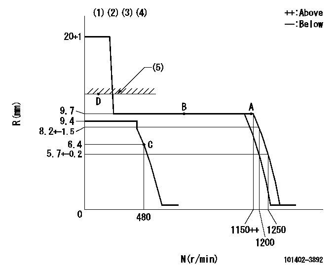
Test data Ex:
Governor adjustment

N:Pump speed
R:Rack position (mm)
(1)Notch fixed: K
(2)Tolerance for racks not indicated: +-0.05mm.
(3)The torque control spring does not operate.
(4)Adjust the secondary timing before adjusting the governor.
(5)RACK LIMIT
----------
K=15
----------
----------
K=15
----------
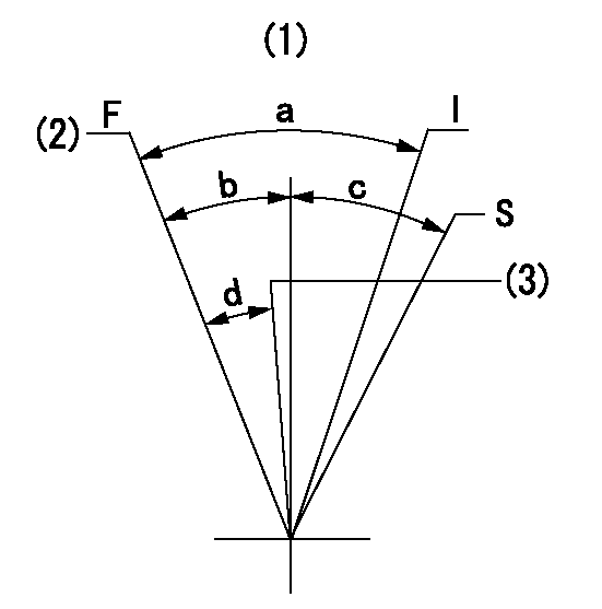
Speed control lever angle

F:Full speed
I:Idle
S:Stop
(1)At hole above R = aa (center)
(2)Speed = bb (push-button power increase)
(3)Speed = cc (active mode).
----------
aa=80mm bb=1250r/min cc=1200r/min
----------
a=(36deg)+-5deg b=(21deg)+-3deg c=32deg+-3deg d=(3deg)+-5deg
----------
aa=80mm bb=1250r/min cc=1200r/min
----------
a=(36deg)+-5deg b=(21deg)+-3deg c=32deg+-3deg d=(3deg)+-5deg
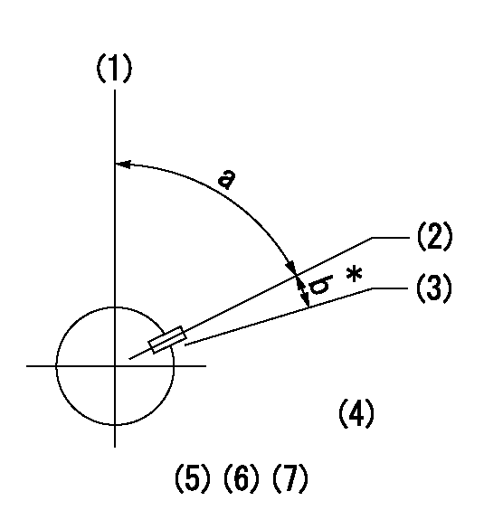
Timing setting

(1)Pump vertical direction
(2)Key groove position at No. 1 cylinder's beginning of injection position (at BTDC: aa).
(3)Position of the key groove of the No. 1 cylinder at B.T.D.C. bb (fix the governor flyweight at this position for delivery).
(4)B.T.D.C.: aa
(5)At second timing adjustment, set the camshaft at the * position and tighten the flyweight locknut.
(6)Align the flyweight's timing gear position with the lockpin groove and then fully tighten the flyweight to the camshaft.
(7)Remove the lock pin and adjust the governor. Reinstall the lock pin to fix the flyweight for delivery.
----------
aa=16deg bb=0deg
----------
a=54deg54min+-3deg b=8deg+-30min
----------
aa=16deg bb=0deg
----------
a=54deg54min+-3deg b=8deg+-30min
Information:
PARTS NEEDED
Obtain etrim files from SIS Web by entering injectorserial numbers. Use the above cross reference table.ACTION REQUIRED
Find engine serial number and injector serialnumber/cylinder location from list.
Download new corrected etrim file from SIS Web.
Install updated etrim file to ECM.
Update power settings FLS/FTS per list.
OWNER NOTIFICATION
U.S. and Canadian owners will receive the attachedOwner Notification.SERVICE CLAIM ALLOWANCES
Caterpillar Dealer Suggested Customer Suggested
Parts Labor Hrs. Parts Labor Hrs. Parts Labor Hrs.
100% 1.0 0 0 0 0
This is a 1.0-hour job. U.S. and Canadian Dealers Only - Eligibledealers may enter a Type 2 SIMS ReportPARTS DISPOSITION
Handle the parts in accordance with your WarrantyBulletin on warranty parts handling.MAKE EVERY EFFORT TO COMPLETE THIS PROGRAMAS SOON AS POSSIBLE.Attach. (1-Owner Notification)COPY OF OWNER NOTIFICATION FOR U.S. AND CANADIAN OWNERS
XYZ Corporation
3240 Arrow Drive
Anywhere, YZ 99999PRIORITY - PRODUCT IMPROVEMENT PROGRAM FORINSTALLING ETRIM FILES ON FUEL INJECTORSMODELS INVOLVED - CERTAIN C7 TRUCK ENGINESDear Caterpillar Product Owner:New software files need to be installed onthe products listed below. The engines provided contain incorrect softwarefiles. You will not be charged for the service performed.Contact your local Caterpillar dealer immediatelyto schedule this service. The dealer will advise you of the time requiredto complete this service. Please refer the dealer to their Service Letterdated January 26, 2004 when scheduling this service.We regret the inconvenience this may causeyou, but urge you to have this service performed as soon as possible toprevent unscheduled downtime.Caterpillar Inc.
Identification #(s)Attached to January 26, 2004 Service Letter
Have questions with 101402-3892?
Group cross 101402-3892 ZEXEL
Komatsu
101402-3892
INJECTION-PUMP ASSEMBLY