Information injection-pump assembly
ZEXEL
101402-3761
1014023761
KOMATSU
6732711111
6732711111
Rating:
Cross reference number
ZEXEL
101402-3761
1014023761
KOMATSU
6732711111
6732711111
Zexel num
Bosch num
Firm num
Name
101402-3761
6732711111 KOMATSU
INJECTION-PUMP ASSEMBLY
S4D102E * K
S4D102E * K
Calibration Data:
Adjustment conditions
Test oil
1404 Test oil ISO4113 or {SAEJ967d}
1404 Test oil ISO4113 or {SAEJ967d}
Test oil temperature
degC
40
40
45
Nozzle and nozzle holder
105780-8140
Bosch type code
EF8511/9A
Nozzle
105780-0000
Bosch type code
DN12SD12T
Nozzle holder
105780-2080
Bosch type code
EF8511/9
Opening pressure
MPa
17.2
Opening pressure
kgf/cm2
175
Injection pipe
Outer diameter - inner diameter - length (mm) mm 6-2-600
Outer diameter - inner diameter - length (mm) mm 6-2-600
Overflow valve
131424-3420
Overflow valve opening pressure
kPa
255
221
289
Overflow valve opening pressure
kgf/cm2
2.6
2.25
2.95
Tester oil delivery pressure
kPa
157
157
157
Tester oil delivery pressure
kgf/cm2
1.6
1.6
1.6
Direction of rotation (viewed from drive side)
Right R
Right R
Injection timing adjustment
Direction of rotation (viewed from drive side)
Right R
Right R
Injection order
1-3-4-2
Pre-stroke
mm
2.5
2.45
2.55
Beginning of injection position
Drive side NO.1
Drive side NO.1
Difference between angles 1
Cal 1-3 deg. 90 89.5 90.5
Cal 1-3 deg. 90 89.5 90.5
Difference between angles 2
Cal 1-4 deg. 180 179.5 180.5
Cal 1-4 deg. 180 179.5 180.5
Difference between angles 3
Cyl.1-2 deg. 270 269.5 270.5
Cyl.1-2 deg. 270 269.5 270.5
Injection quantity adjustment
Adjusting point
A
Rack position
9.2
Pump speed
r/min
1100
1100
1100
Average injection quantity
mm3/st.
79.5
78.5
80.5
Max. variation between cylinders
%
0
-2.5
2.5
Basic
*
Fixing the lever
*
Boost pressure
kPa
38.7
38.7
Boost pressure
mmHg
290
290
Hydraulic cylinder ON
*
Injection quantity adjustment_02
Adjusting point
C
Rack position
7.2+-0.5
Pump speed
r/min
450
450
450
Average injection quantity
mm3/st.
12.5
11.5
13.5
Max. variation between cylinders
%
0
-15
15
Fixing the rack
*
Boost pressure
kPa
0
0
0
Boost pressure
mmHg
0
0
0
Hydraulic cylinder ON
*
Injection quantity adjustment_03
Adjusting point
D
Rack position
-
Pump speed
r/min
100
100
100
Average injection quantity
mm3/st.
60
60
70
Fixing the lever
*
Boost pressure
kPa
0
0
0
Boost pressure
mmHg
0
0
0
Hydraulic cylinder OFF
*
Rack limit
*
Boost compensator adjustment
Pump speed
r/min
750
750
750
Rack position
R1-0.3
Boost pressure
kPa
18.7
16
21.4
Boost pressure
mmHg
140
120
160
Boost compensator adjustment_02
Pump speed
r/min
750
750
750
Rack position
R1(9.2)
Boost pressure
kPa
25.3
25.3
25.3
Boost pressure
mmHg
190
190
190
Test data Ex:
Governor adjustment
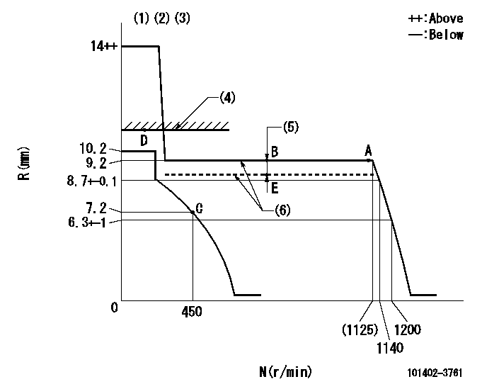
N:Pump speed
R:Rack position (mm)
(1)Target notch: K
(2)Tolerance for racks not indicated: +-0.05mm.
(3)Adjust the secondary timing before adjusting the governor.
(4)RACK LIMIT (When hydraulic cylinder is OFF)
(5)Boost compensator stroke: BCL
(6)When hydraulic cylinder ON: P1
----------
K=11 BCL=0.3+-0.1mm P1=((392)kPa,(4)kgf/cm2)
----------
----------
K=11 BCL=0.3+-0.1mm P1=((392)kPa,(4)kgf/cm2)
----------
Speed control lever angle
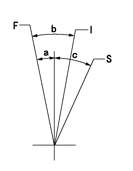
F:Full speed
I:Idle
S:Stop
----------
----------
a=7deg+-3deg b=32deg+-5deg c=35deg+-3deg
----------
----------
a=7deg+-3deg b=32deg+-5deg c=35deg+-3deg
Stop lever angle
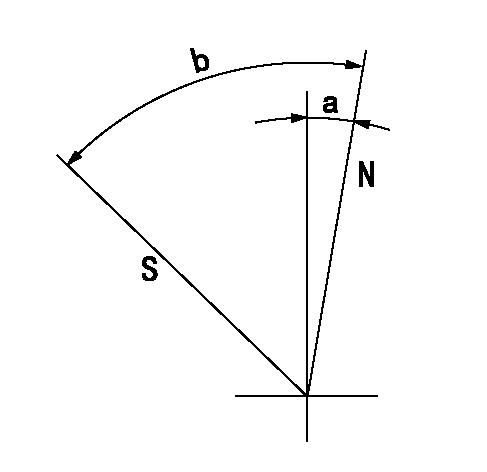
N:Pump normal
S:Stop the pump.
----------
----------
a=0deg+-5deg b=53deg+-5deg
----------
----------
a=0deg+-5deg b=53deg+-5deg
Timing setting
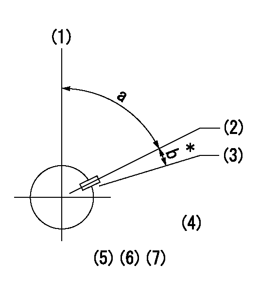
(1)Pump vertical direction
(2)Key groove position at No. 1 cylinder's beginning of injection position (at BTDC: aa).
(3)Position of the key groove of the No. 1 cylinder at B.T.D.C. bb (fix the governor flyweight at this position for delivery).
(4)B.T.D.C.: aa
(5)At second timing adjustment, set the camshaft at the * position and tighten the flyweight locknut.
(6)Align the flyweight's timing gear position with the lockpin groove and then fully tighten the flyweight to the camshaft.
(7)Remove the lock pin and adjust the governor. Reinstall the lock pin to fix the flyweight for delivery.
----------
aa=17deg bb=0deg
----------
a=54deg54min+-3deg b=8deg30min+-30min
----------
aa=17deg bb=0deg
----------
a=54deg54min+-3deg b=8deg30min+-30min
Information:
Problem
Some 1007556 Nozzle Assemblies may experience a fuel rate loss with a resultant complaint of low power on certain 415/425 hp 3406C Engines.
Affected Product
Model & Identification Number
3406C 3ZJ 36410-52109
Parts Needed
6 - 0R4337 Nozzle AssembliesAction Required
See attached rework procedure.
Service Claim Allowances
This is an 8.4-hour job. If the engine is equipped with a Jake Brake, an addition hour of labor may be claimed.
Parts Disposition
Handle the parts in accordance with your Warranty Bulletin on warranty parts handling.
Attach.(1-Rework Procedure)Rework Procedure
This Program only applies after a customer lodges a complaint concerning engine performance (either a lack of horsepower or poor fuel economy).
1. Conduct a customer interview to determine the exact basis of the complaint. Begin by asking "Why are you saying that you have a performance complaint?"A. If the customer's answers indicate a horsepower loss over time, or are specific and similar to the examples listed below, go to Step 2: A 10% fuel mileage decrease (0.5 to 0.7 mpg) is normal when comparing winter to summer operation, assuming the application of the tractor did not change (same loads, speed, idle time, etc. ...).
This procedure is not intended to correct a 1 mpg fuel economy complaint. Such complaints are usually not engine related.
B. If the customer's answers do not indicate a horsepower loss over time, are not specific nor similar to the examples listed below, STOP this Program does not apply: 2. Determine if new 1007600 Nozzle Assemblies (or 0R4337 Nozzle Assemblies) were installed in this engine during a previous repair? 3. Determine if the FARC (Fuel / Air Ratio Control) setting changed during a previous repair? 4. Perform the basic checks listed below. While performing these basic checks, the engine should NOT be operating. Some of the basic checks may have to rely on the customer's perception. The intent of the basic checks is to eliminate obvious functional problems before performing the dynamometer test. If the basic checks are all OK, go to Step 5. If the basic checks are NOT OK, fix the problem item(s). If the customer is satisfied after the basic check problem item(s) are fixed, STOP. If the customer is still unsatisfied after the basic check problem(s) are fixed, go to Step 5.
5. Perform a PAR dynamometer test. The fuel rates charts below are corrected to EPA certified fuel rates for the performance specifications and serial number ranges involved in this rework. If the engine performance is within the PAR specification band, the customer is responsible for the expense of the PAR test. If the engine performance is outside of the PAR specification band, install six 0R4337 Nozzle Assemblies
Fuel Rates
Have questions with 101402-3761?
Group cross 101402-3761 ZEXEL
Komatsu
101402-3761
6732711111
INJECTION-PUMP ASSEMBLY
S4D102E
S4D102E