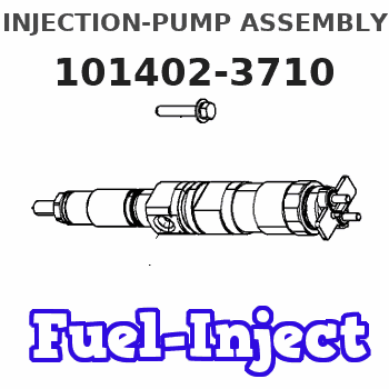
Information injection-pump assembly
ZEXEL
101402-3710
1014023710
KOMATSU
6135711410
6135711410
Rating:
Service parts 101402-3710 INJECTION-PUMP ASSEMBLY:
1.
_
5.
AUTOM. ADVANCE MECHANIS
6.
COUPLING PLATE
7.
COUPLING PLATE
8.
_
9.
_
11.
Nozzle and Holder
6137-12-3100
12.
Open Pre:MPa(Kqf/cm2)
22.1{225}

15.
NOZZLE SET
Cross reference number
ZEXEL
101402-3710
1014023710
KOMATSU
6135711410
6135711410
Zexel num
Bosch num
Firm num
Name
101402-3710
6135711410 KOMATSU
INJECTION-PUMP ASSEMBLY
S4D105 * K
S4D105 * K
Calibration Data:
Adjustment conditions
Test oil
1404 Test oil ISO4113 or {SAEJ967d}
1404 Test oil ISO4113 or {SAEJ967d}
Test oil temperature
degC
40
40
45
Nozzle and nozzle holder
105780-8140
Bosch type code
EF8511/9A
Nozzle
105780-0000
Bosch type code
DN12SD12T
Nozzle holder
105780-2080
Bosch type code
EF8511/9
Opening pressure
MPa
17.2
Opening pressure
kgf/cm2
175
Injection pipe
Outer diameter - inner diameter - length (mm) mm 6-2-600
Outer diameter - inner diameter - length (mm) mm 6-2-600
Tester oil delivery pressure
kPa
157
157
157
Tester oil delivery pressure
kgf/cm2
1.6
1.6
1.6
Direction of rotation (viewed from drive side)
Right R
Right R
Injection timing adjustment
Direction of rotation (viewed from drive side)
Right R
Right R
Injection order
1-2-4-3
Pre-stroke
mm
3.3
3.25
3.35
Beginning of injection position
Drive side NO.1
Drive side NO.1
Difference between angles 1
Cyl.1-2 deg. 90 89.5 90.5
Cyl.1-2 deg. 90 89.5 90.5
Difference between angles 2
Cal 1-4 deg. 180 179.5 180.5
Cal 1-4 deg. 180 179.5 180.5
Difference between angles 3
Cal 1-3 deg. 270 269.5 270.5
Cal 1-3 deg. 270 269.5 270.5
Injection quantity adjustment
Adjusting point
A
Rack position
11
Pump speed
r/min
1250
1250
1250
Average injection quantity
mm3/st.
72
71
73
Max. variation between cylinders
%
0
-2
2
Basic
*
Fixing the lever
*
Injection quantity adjustment_02
Adjusting point
B
Rack position
7.8+-0.5
Pump speed
r/min
300
300
300
Average injection quantity
mm3/st.
10
9
11
Max. variation between cylinders
%
0
-10
10
Fixing the rack
*
Test data Ex:
Governor adjustment
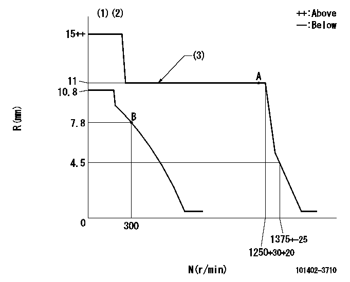
N:Pump speed
R:Rack position (mm)
(1)Target notch: K
(2)Do not adjust boost compensator spring.
(3)The torque control spring does not operate.
----------
K=4
----------
----------
K=4
----------
Speed control lever angle
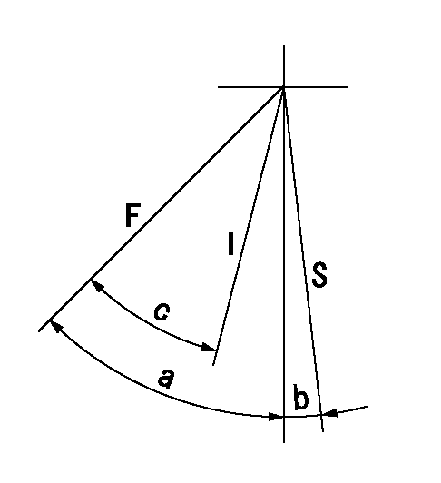
F:Full speed
I:Idle
S:Stop
----------
----------
a=(41deg)+-5deg b=0deg+-3deg c=(32deg)+-5deg
----------
----------
a=(41deg)+-5deg b=0deg+-3deg c=(32deg)+-5deg
Stop lever angle

N:Pump normal
S:Stop the pump.
----------
----------
a=23deg+-5deg b=50deg+-5deg
----------
----------
a=23deg+-5deg b=50deg+-5deg
Timing setting

(1)Pump vertical direction
(2)Position of center of spline's wide tooth at No 1 cylinder's beginning of injection (key position)
(3)-
(4)-
----------
----------
a=(1deg)
----------
----------
a=(1deg)
Information:
Problem
Problems with startability and rough operation immediately following initial start up may occur on certain 3408 and 3412 Marine Engines. Also, these engines may experience a power loss due to high pressure leakage at the fuel injection pump bonnets.
Affected Product
Model & Identification Number
3408B (8RG1-120)
3412 (3JK1-60, 3JK63-75, 3JK77-81, 3JK83-176)
Parts Needed
8 - 7E4847 Seal (for 3408B, 12 for 3412)2 - 4F7957 Capscrew8 - 6I1665 Bonnet (for 3408B, 12 for 3412)2 - 3J7354 Seal-O-Ring2 - 5P0537 Washer2 - 5P2645 Elbow2 - 2V3216 Clip1 - 058593 Seal1 - 1083795 Cover-Oil Pump1 - 1083796 Cover-Bypass1 - 1083964 Line Assembly1 - 1084420 Gasket-Bypass CoverAction Required
See attached rework procedure.
Service Claim Allowances
This is a 6-hour job.
Parts Disposition
Handle the parts in accordance with your Warranty Bulletin on warranty parts handling.
Attach. (1-Rework Procedure)Rework Procedure
1. Remove the 9Y6037 Cover Assembly from the rear section of the fuel injection and governor group. Save the 2-1B2714, 2-1B2713, and 1-7B8167 Bolts.2. Remove the 9Y6036 Cover from the top of the 9Y6037 Cover Assembly to reveal the 4N0605 Spring and 4N1767 Valve. Clean and save the spring and valve in addition to the 1-0S1616 Bolt and 1-9F7022 Bolt for reuse.3. Install the spring and valve in the new 1083796 Cover Assembly. Install (dry) a new 1084420 Gasket. Use the 1-0S1616 Bolt and 1-9F7022 Bolt to assemble 1083796 Cover to the 1083795 Cover. See Illustration 1.
Illustration 14. Install the new assembly where the previous assembly was removed from the pump group reusing the bolts from Step 1. Use a new 0058593 Seal when installing the cover assembly onto the injection pump. See Illustration 2.5. Install a 3J7354 Seal onto each 5P2645 Elbow. Install an elbow into each threaded port in the cover assembly but do not tighten, yet.6. Remove the two existing 0S1615 Bolts from the fuel gallery cover as shown in Illustration 2. Install the 2-2V3216 Clips onto the 1083964 Line Assembly so they line up with the bolt holes on the fuel gallery cover.7. Install the 1083694 Line Assembly onto the two elbows. Install 2-4F7957 Bolts and 2-5P0537 Washers through the clips and into the pump housing.8. Tighten the elbows to the covers and tighten the line assembly nuts onto the elbows. Tighten the clip retaining bolts using standard bolt torque.
Illustration 29. Zero the injection pump racks and pin them in place. Remove the fuel injection lines from the pump bonnets.10. Remove 4P2899 Bushings and 4P7681 Pump Groups from the fuel injection pump. Identify the bushings and pump groups so that they can be installed in the same holes from which they were removed.11. Remove the existing 2W3409 Bonnets from the 4P7681 Pump Groups and install new 6I1665 Bonnets as shown in Illustration 3. If the barrel face of an individual injection pump is stained, the face may be lapped. Use 600 grit abrasive and lap the face on a flat surface in a figure 8 pattern. Lap the barrel face no more than 10 times in the figure 8 motion. If the stains still remain, replace the 7E6007 Plunger and Barrel
Have questions with 101402-3710?
Group cross 101402-3710 ZEXEL
Komatsu
101402-3710
6135711410
INJECTION-PUMP ASSEMBLY
S4D105
S4D105