Information injection-pump assembly
ZEXEL
101402-3460
1014023460
KOMATSU
6131721310
6131721310
Rating:
Service parts 101402-3460 INJECTION-PUMP ASSEMBLY:
1.
_
5.
AUTOM. ADVANCE MECHANIS
6.
COUPLING PLATE
8.
_
9.
_
11.
Nozzle and Holder
6131-12-3100
12.
Open Pre:MPa(Kqf/cm2)
22.1{225}
15.
NOZZLE SET
Cross reference number
ZEXEL
101402-3460
1014023460
KOMATSU
6131721310
6131721310
Zexel num
Bosch num
Firm num
Name
Calibration Data:
Adjustment conditions
Test oil
1404 Test oil ISO4113 or {SAEJ967d}
1404 Test oil ISO4113 or {SAEJ967d}
Test oil temperature
degC
40
40
45
Nozzle and nozzle holder
105780-8140
Bosch type code
EF8511/9A
Nozzle
105780-0000
Bosch type code
DN12SD12T
Nozzle holder
105780-2080
Bosch type code
EF8511/9
Opening pressure
MPa
17.2
Opening pressure
kgf/cm2
175
Injection pipe
Outer diameter - inner diameter - length (mm) mm 6-2-600
Outer diameter - inner diameter - length (mm) mm 6-2-600
Tester oil delivery pressure
kPa
157
157
157
Tester oil delivery pressure
kgf/cm2
1.6
1.6
1.6
Direction of rotation (viewed from drive side)
Right R
Right R
Injection timing adjustment
Direction of rotation (viewed from drive side)
Right R
Right R
Injection order
1-2-4-3
Pre-stroke
mm
3.5
3.45
3.55
Beginning of injection position
Governor side NO.1
Governor side NO.1
Difference between angles 1
Cyl.1-2 deg. 90 89.5 90.5
Cyl.1-2 deg. 90 89.5 90.5
Difference between angles 2
Cal 1-4 deg. 180 179.5 180.5
Cal 1-4 deg. 180 179.5 180.5
Difference between angles 3
Cal 1-3 deg. 270 269.5 270.5
Cal 1-3 deg. 270 269.5 270.5
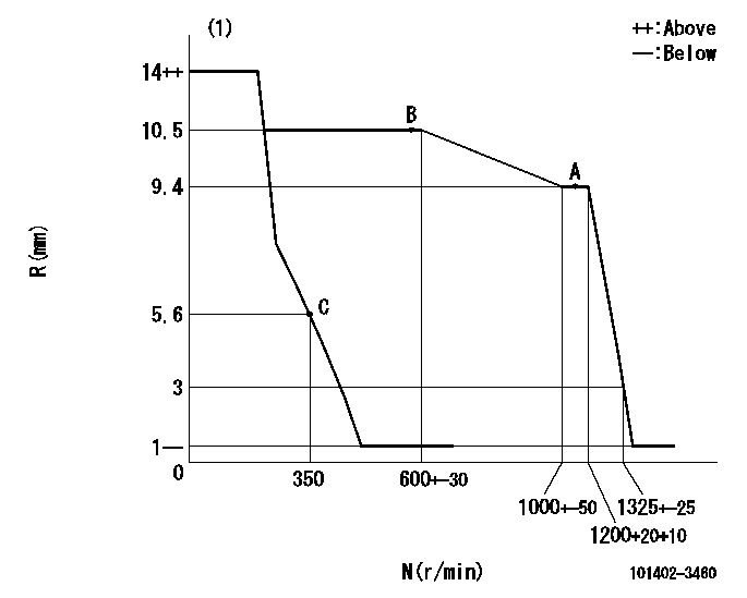
Injection quantity adjustment
Adjusting point
A
Rack position
9.4
Pump speed
r/min
1200
1200
1200
Average injection quantity
mm3/st.
73.5
71.5
75.5
Max. variation between cylinders
%
0
-2
2
Basic
*
Fixing the rack
*
Injection quantity adjustment_02
Adjusting point
B
Rack position
10.5
Pump speed
r/min
600
600
600
Average injection quantity
mm3/st.
74.5
70.5
78.5
Max. variation between cylinders
%
0
-4
4
Fixing the lever
*
Injection quantity adjustment_03
Adjusting point
C
Rack position
5.6+-0.5
Pump speed
r/min
350
350
350
Average injection quantity
mm3/st.
15
13
17
Max. variation between cylinders
%
0
-10
10
Fixing the rack
*
Test data Ex:
Governor adjustment
N:Pump speed
R:Rack position (mm)
(1)Target notch: K
----------
K=10
----------
----------
K=10
----------
Speed control lever angle
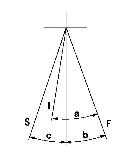
F:Full speed
I:Idle
S:Stop
----------
----------
a=31deg+-3deg b=16deg+-5deg c=32deg+-3deg
----------
----------
a=31deg+-3deg b=16deg+-5deg c=32deg+-3deg
Information:
Removal Procedure
Contact with high pressure fuel may cause fluid penetration and burn hazards. High pressure fuel spray may cause a fire hazard. Failure to follow these inspection, maintenance and service instructions may cause personal injury or death.
Ensure that all adjustments and repairs that are carried out to the fuel system are performed by authorised personnel that have the correct training.Before begining ANY work on the fuel system, refer to Operation and Maintenance Manual, "General Hazard Information and High Pressure Fuel Lines" for safety information.Refer to Systems Operation, Testing and Adjusting Manual, "Cleanliness of Fuel System Components" for detailed information on the standards of cleanliness that must be observed during ALL work on the fuel system.
Care must be taken to ensure that fluids are contained during performance of inspection, maintenance, testing, adjusting and repair of the product. Be