Information injection-pump assembly
BOSCH
9 400 613 428
9400613428
ZEXEL
101402-3452
1014023452
KOMATSU
6131721212
6131721212
Rating:
Service parts 101402-3452 INJECTION-PUMP ASSEMBLY:
1.
_
5.
AUTOM. ADVANCE MECHANIS
6.
COUPLING PLATE
8.
_
9.
_
11.
Nozzle and Holder
6-13112-310-0
12.
Open Pre:MPa(Kqf/cm2)
15.
NOZZLE SET
Cross reference number
BOSCH
9 400 613 428
9400613428
ZEXEL
101402-3452
1014023452
KOMATSU
6131721212
6131721212
Zexel num
Bosch num
Firm num
Name
101402-3452
9 400 613 428
6131721212 KOMATSU
INJECTION-PUMP ASSEMBLY
S4D105 K
S4D105 K
Calibration Data:
Adjustment conditions
Test oil
1404 Test oil ISO4113 or {SAEJ967d}
1404 Test oil ISO4113 or {SAEJ967d}
Test oil temperature
degC
40
40
45
Nozzle and nozzle holder
105780-8140
Bosch type code
EF8511/9A
Nozzle
105780-0000
Bosch type code
DN12SD12T
Nozzle holder
105780-2080
Bosch type code
EF8511/9
Opening pressure
MPa
17.2
Opening pressure
kgf/cm2
175
Injection pipe
Outer diameter - inner diameter - length (mm) mm 6-2-600
Outer diameter - inner diameter - length (mm) mm 6-2-600
Tester oil delivery pressure
kPa
157
157
157
Tester oil delivery pressure
kgf/cm2
1.6
1.6
1.6
Direction of rotation (viewed from drive side)
Right R
Right R
Injection timing adjustment
Direction of rotation (viewed from drive side)
Right R
Right R
Injection order
1-2-4-3
Pre-stroke
mm
3.5
3.45
3.55
Rack position
After adjusting injection quantity. R=A
After adjusting injection quantity. R=A
Beginning of injection position
Governor side NO.1
Governor side NO.1
Difference between angles 1
Cyl.1-2 deg. 90 89.5 90.5
Cyl.1-2 deg. 90 89.5 90.5
Difference between angles 2
Cal 1-4 deg. 180 179.5 180.5
Cal 1-4 deg. 180 179.5 180.5
Difference between angles 3
Cal 1-3 deg. 270 269.5 270.5
Cal 1-3 deg. 270 269.5 270.5
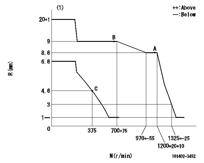
Injection quantity adjustment
Adjusting point
A
Rack position
8.6
Pump speed
r/min
1200
1200
1200
Average injection quantity
mm3/st.
85
83
87
Max. variation between cylinders
%
0
-2
2
Basic
*
Fixing the rack
*
Injection quantity adjustment_02
Adjusting point
B
Rack position
9
Pump speed
r/min
700
700
700
Average injection quantity
mm3/st.
83
83
88
Max. variation between cylinders
%
0
-4
4
Fixing the lever
*
Injection quantity adjustment_03
Adjusting point
C
Rack position
4.6+-0.5
Pump speed
r/min
375
375
375
Average injection quantity
mm3/st.
10
8
12
Max. variation between cylinders
%
0
-10
10
Fixing the rack
*
Test data Ex:
Governor adjustment
N:Pump speed
R:Rack position (mm)
(1)Target notch: K
----------
K=15
----------
----------
K=15
----------
Speed control lever angle

F:Full speed
I:Idle
S:Stop
----------
----------
a=16deg+-5deg b=32deg+-3deg c=23deg+-5deg
----------
----------
a=16deg+-5deg b=32deg+-3deg c=23deg+-5deg
Timing setting

(1)Pump vertical direction
(2)Position of center of spline's wide tooth at No 1 cylinder's beginning of injection (key position)
(3)B.T.D.C.: aa
(4)-
----------
aa=21deg
----------
a=(30deg)
----------
aa=21deg
----------
a=(30deg)
Information:
Important Safety Information
Illustration 1 g02139237Work safely. Most accidents that involve product operation, maintenance, and repair are caused by failure to observe basic safety rules or precautions. An accident can often be avoided by recognizing potentially hazardous situations before an accident occurs. A person must be alert to potential hazards. This person should also have the necessary training, skills, and tools to perform these functions properly. Safety precautions and warnings are provided in this instruction and on the product. If these hazard warnings are not heeded, bodily injury or death could occur to you or to other persons. Caterpillar cannot anticipate every possible circumstance that might involve a potential hazard. Therefore, the warnings in this publication and the warnings that are on the product are not all inclusive. If a tool, a procedure, a work method, or operating technique that is not recommended by Caterpillar is used, ensure that it is safe for you and for other people to use. Ensure that the product will not be damaged or the product will not be made unsafe by the operation, lubrication, maintenance, or the repair procedures that are used.
Improper operation, lubrication, maintenance or repair of this product can be dangerous and could result in injury or death.Do not operate or perform any lubrication, maintenance or repair on this product, until you have read and understood the operation, lubrication, maintenance and repair information.
Safety precautions and warnings are provided in this manual and on the product. If these hazard warnings are not heeded, bodily injury or death could occur to you or to other persons.The hazards are identified by the safety alert symbol which is followed by a signal word such as danger, warning, or caution. The "" safety alert symbol is shown below.
Illustration 2 g00008666This safety alert symbol means:Pay attention!Become alert!Your safety is involved.The message that appears under the safety alert symbol explains the hazard.Operations that may cause product damage are identified by "" labels on the product and in this publication.Caterpillar cannot anticipate every possible circumstance that might involve a potential hazard. The safety information in this document and the safety information on the machine are not all inclusive. Determine that the tools, procedures, work methods, and operating techniques are safe. Determine that the operation, lubrication, maintenance, and repair procedures will not damage the machine. Also, you must determine that the operation, lubrication, maintenance, and repair procedures will not make the machine unsafe.The information, the specifications, and the illustrations that exist in this guideline are based on information which was available at the time of publication. The specifications, torques, pressures, measurements, adjustments, illustrations, and other items can change at any time. These changes can affect the service that is given to the product. Obtain the complete, most current information before you start any job. Caterpillar dealers can supply the most current information.Summary
The information included in this guideline should serve as an aid in fuel injection pump housing test procedure.Service Letters and Technical Information Bulletins
The most recent Service Letters and Technical Information Bulletins
Have questions with 101402-3452?
Group cross 101402-3452 ZEXEL
Komatsu
101402-3452
9 400 613 428
6131721212
INJECTION-PUMP ASSEMBLY
S4D105
S4D105