Information injection-pump assembly
BOSCH
9 400 613 427
9400613427
ZEXEL
101402-3442
1014023442
KOMATSU
6131721112
6131721112
Rating:
Service parts 101402-3442 INJECTION-PUMP ASSEMBLY:
1.
_
5.
AUTOM. ADVANCE MECHANIS
6.
COUPLING PLATE
8.
_
9.
_
11.
Nozzle and Holder
6-13112-310-0
12.
Open Pre:MPa(Kqf/cm2)
15.
NOZZLE SET
Cross reference number
BOSCH
9 400 613 427
9400613427
ZEXEL
101402-3442
1014023442
KOMATSU
6131721112
6131721112
Zexel num
Bosch num
Firm num
Name
101402-3442
9 400 613 427
6131721112 KOMATSU
INJECTION-PUMP ASSEMBLY
S4D105 * K
S4D105 * K
Calibration Data:
Adjustment conditions
Test oil
1404 Test oil ISO4113 or {SAEJ967d}
1404 Test oil ISO4113 or {SAEJ967d}
Test oil temperature
degC
40
40
45
Nozzle and nozzle holder
105780-8140
Bosch type code
EF8511/9A
Nozzle
105780-0000
Bosch type code
DN12SD12T
Nozzle holder
105780-2080
Bosch type code
EF8511/9
Opening pressure
MPa
17.2
Opening pressure
kgf/cm2
175
Injection pipe
Outer diameter - inner diameter - length (mm) mm 6-2-600
Outer diameter - inner diameter - length (mm) mm 6-2-600
Tester oil delivery pressure
kPa
157
157
157
Tester oil delivery pressure
kgf/cm2
1.6
1.6
1.6
Direction of rotation (viewed from drive side)
Right R
Right R
Injection timing adjustment
Direction of rotation (viewed from drive side)
Right R
Right R
Injection order
1-2-4-3
Pre-stroke
mm
3.5
3.45
3.55
Rack position
After adjusting injection quantity. R=A
After adjusting injection quantity. R=A
Beginning of injection position
Governor side NO.1
Governor side NO.1
Difference between angles 1
Cyl.1-2 deg. 90 89.5 90.5
Cyl.1-2 deg. 90 89.5 90.5
Difference between angles 2
Cal 1-4 deg. 180 179.5 180.5
Cal 1-4 deg. 180 179.5 180.5
Difference between angles 3
Cal 1-3 deg. 270 269.5 270.5
Cal 1-3 deg. 270 269.5 270.5
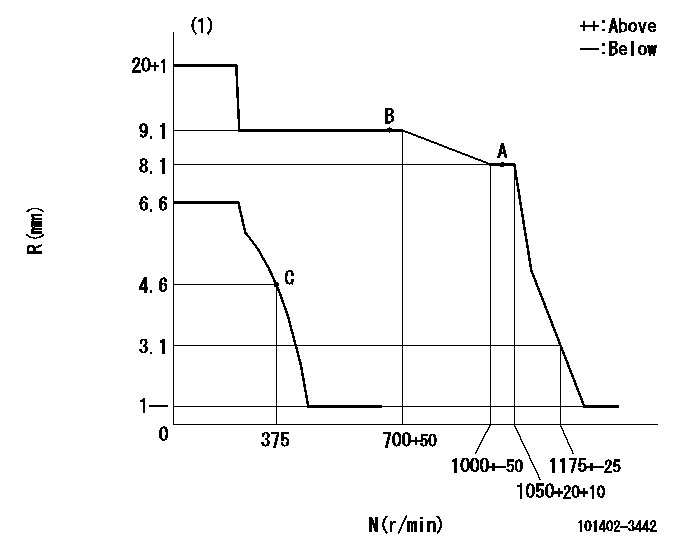
Injection quantity adjustment
Adjusting point
A
Rack position
8.1
Pump speed
r/min
1050
1050
1050
Average injection quantity
mm3/st.
73
71
75
Max. variation between cylinders
%
0
-2
2
Basic
*
Fixing the rack
*
Injection quantity adjustment_02
Adjusting point
B
Rack position
9.1
Pump speed
r/min
700
700
700
Average injection quantity
mm3/st.
80
80
84
Max. variation between cylinders
%
0
-4
4
Fixing the lever
*
Injection quantity adjustment_03
Adjusting point
C
Rack position
4.6+-0.5
Pump speed
r/min
375
375
375
Average injection quantity
mm3/st.
10
8
12
Max. variation between cylinders
%
0
-10
10
Fixing the rack
*
Test data Ex:
Governor adjustment
N:Pump speed
R:Rack position (mm)
(1)Target notch: K
----------
K=15
----------
----------
K=15
----------
Speed control lever angle

F:Full speed
I:Idle
S:Stop
----------
----------
a=12deg+-5deg b=32deg+-3deg c=19deg+-5deg
----------
----------
a=12deg+-5deg b=32deg+-3deg c=19deg+-5deg
Timing setting

(1)Pump vertical direction
(2)Position of center of spline's wide tooth at No 1 cylinder's beginning of injection (key position)
(3)B.T.D.C.: aa
(4)-
----------
aa=21deg
----------
a=(30deg)
----------
aa=21deg
----------
a=(30deg)
Information:
Do not operate or work on this product unless you have read and understood the instruction and warnings in the relevant Operation and Maintenance Manuals and relevant service literature. Failure to follow the instructions or heed the warnings could result in injury or death. Proper care is your responsibility.
Table 1
Existing Part Number New Part Number Description
459-7216 471-6029 DEF Injector & Mounting Gp
540-0883 554-8955 24V DEF Pump Software
481-5823 554-8956 12V DEF Pump Software Refer to Disassembly and Assembly, DEF Injector and Mounting - Remove and Install for the correct procedure to install the new DEF injector.Refer to Troubleshooting, ECM Software - Install for the correct procedure to install the new software.
Have questions with 101402-3442?
Group cross 101402-3442 ZEXEL
Komatsu
101402-3442
9 400 613 427
6131721112
INJECTION-PUMP ASSEMBLY
S4D105
S4D105