Information injection-pump assembly
BOSCH
9 400 613 873
9400613873
ZEXEL
101402-2460
1014022460
HINO
220206440A
220206440a
Rating:
Service parts 101402-2460 INJECTION-PUMP ASSEMBLY:
1.
_
5.
AUTOM. ADVANCE MECHANIS
6.
COUPLING PLATE
8.
_
9.
_
11.
Nozzle and Holder
12.
Open Pre:MPa(Kqf/cm2)
15.7(160)/21.6(220)
14.
NOZZLE
Cross reference number
BOSCH
9 400 613 873
9400613873
ZEXEL
101402-2460
1014022460
HINO
220206440A
220206440a
Zexel num
Bosch num
Firm num
Name
101402-2460
9 400 613 873
220206440A HINO
INJECTION-PUMP ASSEMBLY
W04D K 14BD INJECTION PUMP ASSY PE4AD PE
W04D K 14BD INJECTION PUMP ASSY PE4AD PE
Calibration Data:
Adjustment conditions
Test oil
1404 Test oil ISO4113 or {SAEJ967d}
1404 Test oil ISO4113 or {SAEJ967d}
Test oil temperature
degC
40
40
45
Nozzle and nozzle holder
105780-8140
Bosch type code
EF8511/9A
Nozzle
105780-0000
Bosch type code
DN12SD12T
Nozzle holder
105780-2080
Bosch type code
EF8511/9
Opening pressure
MPa
17.2
Opening pressure
kgf/cm2
175
Injection pipe
Outer diameter - inner diameter - length (mm) mm 6-2-600
Outer diameter - inner diameter - length (mm) mm 6-2-600
Overflow valve
131424-5720
Overflow valve opening pressure
kPa
255
221
289
Overflow valve opening pressure
kgf/cm2
2.6
2.25
2.95
Tester oil delivery pressure
kPa
255
255
255
Tester oil delivery pressure
kgf/cm2
2.6
2.6
2.6
Direction of rotation (viewed from drive side)
Right R
Right R
Injection timing adjustment
Direction of rotation (viewed from drive side)
Right R
Right R
Injection order
1-3-4-2
Pre-stroke
mm
4.8
4.75
4.85
Beginning of injection position
Drive side NO.1
Drive side NO.1
Difference between angles 1
Cal 1-3 deg. 90 89.5 90.5
Cal 1-3 deg. 90 89.5 90.5
Difference between angles 2
Cal 1-4 deg. 180 179.5 180.5
Cal 1-4 deg. 180 179.5 180.5
Difference between angles 3
Cyl.1-2 deg. 270 269.5 270.5
Cyl.1-2 deg. 270 269.5 270.5
Injection quantity adjustment
Adjusting point
A
Rack position
10.8
Pump speed
r/min
900
900
900
Average injection quantity
mm3/st.
83
81
85
Max. variation between cylinders
%
0
-3
3
Basic
*
Fixing the lever
*
Injection quantity adjustment_02
Adjusting point
-
Rack position
7.5+-0.5
Pump speed
r/min
400
400
400
Average injection quantity
mm3/st.
11.5
10
13
Max. variation between cylinders
%
0
-15
15
Fixing the rack
*
Remarks
Adjust only variation between cylinders; adjust governor according to governor specifications.
Adjust only variation between cylinders; adjust governor according to governor specifications.
Injection quantity adjustment_03
Adjusting point
D
Rack position
11++
Pump speed
r/min
100
100
100
Average injection quantity
mm3/st.
90
90
100
Fixing the lever
*
Rack limit
*
Test data Ex:
Governor adjustment
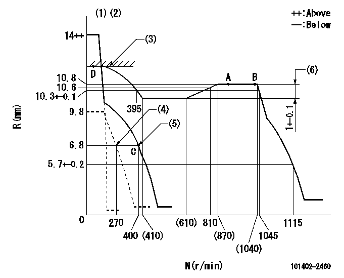
N:Pump speed
R:Rack position (mm)
(1)Target notch: K
(2)Tolerance for racks not indicated: +-0.05mm.
(3)RACK LIMIT
(4)Set idle sub-spring
(5)Main spring setting
(6)Rack difference between N = N1 and N = N2
----------
K=12 N1=900r/min N2=500r/min
----------
----------
K=12 N1=900r/min N2=500r/min
----------
Speed control lever angle
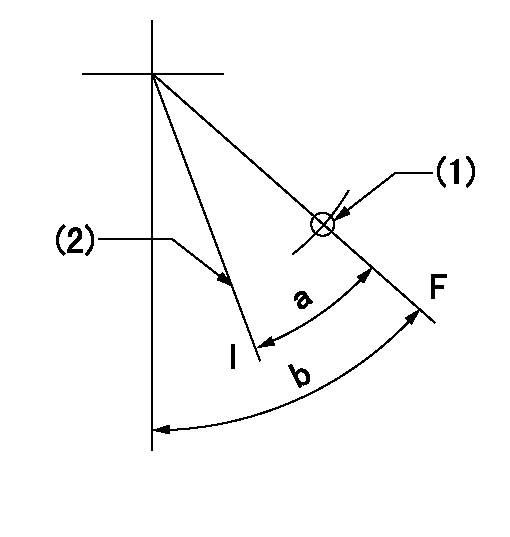
F:Full speed
I:Idle
(1)Use the hole at R = aa
(2)Stopper bolt setting
----------
aa=80mm
----------
a=26deg+-5deg b=52deg+-5deg
----------
aa=80mm
----------
a=26deg+-5deg b=52deg+-5deg
Stop lever angle

N:Pump normal
S:Stop the pump.
(1)Normal
(2)Rack position aa or less, pump speed bb
----------
aa=6.3mm bb=0r/min
----------
a=27deg+-5deg b=53deg+-5deg
----------
aa=6.3mm bb=0r/min
----------
a=27deg+-5deg b=53deg+-5deg
Timing setting

(1)Pump vertical direction
(2)Position of gear's standard threaded hole at No 1 cylinder's beginning of injection
(3)-
(4)-
----------
----------
a=(70deg)
----------
----------
a=(70deg)
Information:
Table 1
Diagnostic Trouble Codes
J1939 Code and Description CDL Code and Description
4334–20
Aftertreatment #1 DEF #1 Pressure (absolute) : Data Drifted High 3090–20
Aftertreatment #1 DEF Pressure Sensor : Data Drifted High
4334-21
Aftertreatment #1 DEF #1 Pressure (absolute) : Data Drifted Low 3090-21
Aftertreatment #1 DEF Pressure Sensor : Data Drifted Low
3361-5
Aftertreatment #1 DEF Dosing Unit : Current Below Normal 3821-5
Aftertreatment #1 Diesel Exhaust Fluid Dosing Valve Actuator : Current Below Normal
3361-6
Aftertreatment #1 DEF Dosing Unit : Current Above Normal 3821-6
Aftertreatment #1 Diesel Exhaust Fluid Dosing Valve Actuator : Current Above Normal
3516-12
Aftertreatment #1 DEF Concentration : Failure 3100-12
Aftertreatment #1 DEF Tank Fluid Quality Sensor : Failure
Table 2
Event Codes
J1939 Code and Description CDL Code and Description
5392-31
Aftertreatment Diesel Exhaust Fluid Dosing Unit Loss of Prime E1370 (2)
Aftertreatment #1 DEF Dosing Unit Loss of Prime
4334-18
Aftertreatment #1 DEF #1 Pressure (absolute) : Low - moderate severity (2) E931 (2)
Low Aftertreatment #1 DEF Pressure
4334-16
Aftertreatment #1 DEF #1 Pressure (absolute) : High - moderate severity (2) E930 (2)
High Aftertreatment #1 DEF Pressure
3516-16
Aftertreatment #1 DEF Concentration : High - moderate severity (2) E1365 (2)
High Aftertreatment #1 DEF Concentration
3516-18
Aftertreatment #1 DEF Concentration : Low - moderate severity (2) E1364 (2)
Low Aftertreatment #1 DEF Concentration
5246-15
Aftertreatment SCR Operator Inducement Severity : High - least severe (1) E1389 (1)
Aftertreatment #1 SCR Operator Inducement
5246-16
Aftertreatment SCR Operator Inducement Severity : High - moderate severity (2) E1389 (2)
Aftertreatment #1 SCR Operator Inducement
5246-0
Aftertreatment SCR Operator Inducement Severity : High - most severe (3) E1389 (3)
Aftertreatment #1 SCR Operator Inducement Ensure that DEF fluid conforms to specification ISO 22241 requirements and fluid handling, filling, and storage procedures are strictly followed.All transfer equipment and storage containers should be used exclusively for DEF and should not be reused for other fluids. For example coolants, fuels, oils, and windshield washer fluid.If contamination of the DEF system is suspected, refer to Troubleshooting, DEF Concentration is Incorrect. Ensure that the correct troubleshooting steps are followed. To test for contamination of the DEF tank, refer to Systems Operation Testing and Adjusting, Diesel Exhaust Fluid Quality - Test.If the DEF is contaminated, Caterpillar recommends that the DEF tank is flushed. Refer to Systems Operation Testing and Adjusting, Diesel Exhaust Fluid Tank - Flush for the correct procedure.
Have questions with 101402-2460?
Group cross 101402-2460 ZEXEL
Hino
101402-2460
9 400 613 873
220206440A
INJECTION-PUMP ASSEMBLY
W04D
W04D