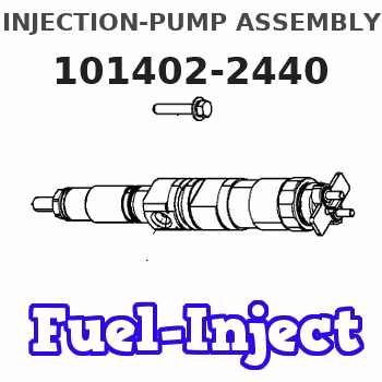
Information injection-pump assembly
BOSCH
9 400 613 872
9400613872
ZEXEL
101402-2440
1014022440
HINO
220206360A
220206360a
Rating:
Include in #1:
108622-3750
as _
Cross reference number
BOSCH
9 400 613 872
9400613872
ZEXEL
101402-2440
1014022440
HINO
220206360A
220206360a
Zexel num
Bosch num
Firm num
Name
9 400 613 872
220206360A HINO
INJECTION-PUMP ASSEMBLY
W04D-TI * K 14BD PE4AD PE
W04D-TI * K 14BD PE4AD PE
Calibration Data:
Adjustment conditions
Test oil
1404 Test oil ISO4113 or {SAEJ967d}
1404 Test oil ISO4113 or {SAEJ967d}
Test oil temperature
degC
40
40
45
Nozzle and nozzle holder
105780-8140
Bosch type code
EF8511/9A
Nozzle
105780-0000
Bosch type code
DN12SD12T
Nozzle holder
105780-2080
Bosch type code
EF8511/9
Opening pressure
MPa
17.2
Opening pressure
kgf/cm2
175
Injection pipe
Outer diameter - inner diameter - length (mm) mm 6-2-600
Outer diameter - inner diameter - length (mm) mm 6-2-600
Overflow valve
131424-5720
Overflow valve opening pressure
kPa
255
221
289
Overflow valve opening pressure
kgf/cm2
2.6
2.25
2.95
Tester oil delivery pressure
kPa
255
255
255
Tester oil delivery pressure
kgf/cm2
2.6
2.6
2.6
Direction of rotation (viewed from drive side)
Right R
Right R
Injection timing adjustment
Direction of rotation (viewed from drive side)
Right R
Right R
Injection order
1-3-4-2
Pre-stroke
mm
4.8
4.75
4.85
Beginning of injection position
Drive side NO.1
Drive side NO.1
Difference between angles 1
Cal 1-3 deg. 90 89.5 90.5
Cal 1-3 deg. 90 89.5 90.5
Difference between angles 2
Cal 1-4 deg. 180 179.5 180.5
Cal 1-4 deg. 180 179.5 180.5
Difference between angles 3
Cyl.1-2 deg. 270 269.5 270.5
Cyl.1-2 deg. 270 269.5 270.5
Injection quantity adjustment
Adjusting point
A
Rack position
11
Pump speed
r/min
1050
1050
1050
Average injection quantity
mm3/st.
121.5
119.5
123.5
Max. variation between cylinders
%
0
-3
3
Basic
*
Fixing the lever
*
Boost pressure
kPa
36
36
Boost pressure
mmHg
270
270
Injection quantity adjustment_02
Adjusting point
-
Rack position
7.8+-0.5
Pump speed
r/min
375
375
375
Average injection quantity
mm3/st.
12
10.5
13.5
Max. variation between cylinders
%
0
-15
15
Fixing the rack
*
Boost pressure
kPa
0
0
0
Boost pressure
mmHg
0
0
0
Remarks
Adjust only variation between cylinders; adjust governor according to governor specifications.
Adjust only variation between cylinders; adjust governor according to governor specifications.
Injection quantity adjustment_03
Adjusting point
E
Rack position
11.2++
Pump speed
r/min
100
100
100
Average injection quantity
mm3/st.
90
90
100
Fixing the lever
*
Boost pressure
kPa
0
0
0
Boost pressure
mmHg
0
0
0
Rack limit
*
Boost compensator adjustment
Pump speed
r/min
600
600
600
Rack position
R1-1.8
Boost pressure
kPa
5.3
2.6
8
Boost pressure
mmHg
40
20
60
Boost compensator adjustment_02
Pump speed
r/min
600
600
600
Rack position
R1(10.5)
Boost pressure
kPa
22.7
22.7
22.7
Boost pressure
mmHg
170
170
170
Test data Ex:
Governor adjustment
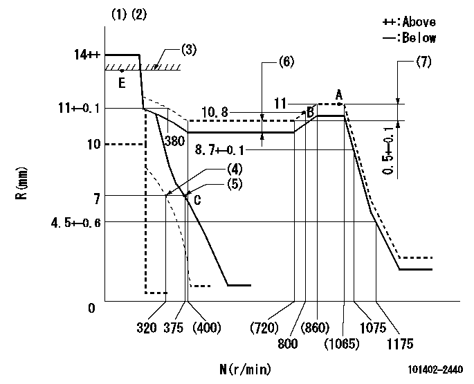
N:Pump speed
R:Rack position (mm)
(1)Target notch: K
(2)Tolerance for racks not indicated: +-0.05mm.
(3)RACK LIMIT
(4)Set idle sub-spring
(5)Main spring setting
(6)Boost compensator stroke: BCL
(7)Rack difference between N = N1 and N = N2
----------
K=14 BCL=1.8+-0.1mm N1=1050r/min N2=600r/min
----------
----------
K=14 BCL=1.8+-0.1mm N1=1050r/min N2=600r/min
----------
Speed control lever angle
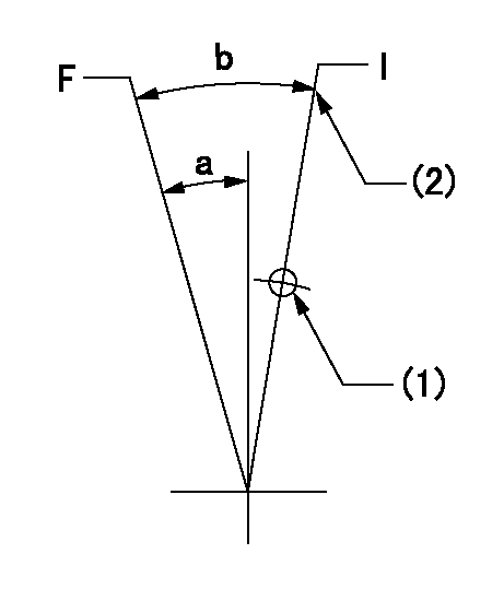
F:Full speed
I:Idle
(1)Use the hole at R = aa
(2)Stopper bolt setting
----------
aa=100mm
----------
a=9deg+-5deg b=25deg+-5deg
----------
aa=100mm
----------
a=9deg+-5deg b=25deg+-5deg
Stop lever angle
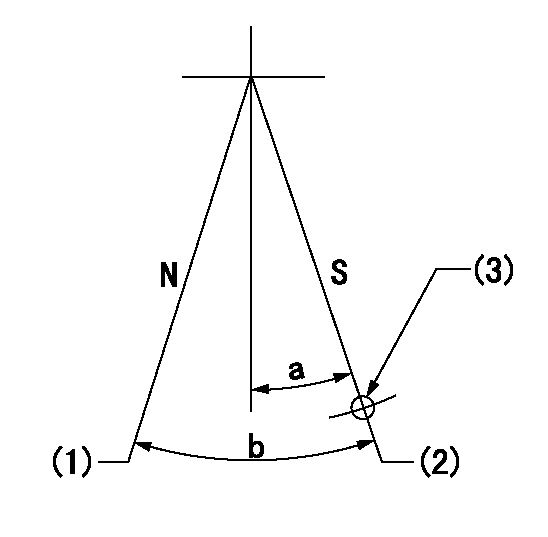
N:Pump normal
S:Stop the pump.
(1)Normal
(2)Pump speed aa and rack position bb (to be sealed at delivery)
(3)Use the hole above R = cc
----------
aa=0r/min bb=1-0.5mm cc=25mm
----------
a=21deg+-5deg b=(55deg)
----------
aa=0r/min bb=1-0.5mm cc=25mm
----------
a=21deg+-5deg b=(55deg)
Timing setting

(1)Pump vertical direction
(2)Position of gear's standard threaded hole at No 1 cylinder's beginning of injection
(3)-
(4)-
----------
----------
a=(70deg)
----------
----------
a=(70deg)
Information:
Introduction
Do not perform any procedure in this Special Instruction until you have read the information and you understand the information.DEF injectors are being replaced in the field and returned to Caterpillar for testing. Results of the testing are finding a large portion of the returned DEF injectors are found to be fault not repeated.This form is to be used and filled out in any case that a DEF injector is being replaced.The DEF injector troubleshooting return form needs to be completed and included within failed part returns documenting what was found that led to DEF injector replacement. Attach the photos of DEF injector tip and mount area along with a Product Status Report to the SIMS claim.References
Table 1
Engine Publication Type Media Number
C7.1 Troubleshooting UENR0668
Testing and Adjusting UENR4467
Disassembly and Assembly UENR4468
C9.3 Troubleshooting UENR0978
Testing and Adjusting UENR3402
Disassembly and Assembly UENR0130
C13 Troubleshooting UENR0955
Testing and Adjusting UENR4302
Disassembly and Assembly UENR0131
C15/C18 Troubleshooting UENR0955
Testing and Adjusting UENR3351
Disassembly and Assembly UENR0132 Procedure
What code are you troubleshooting? __________
Follow the correct troubleshooting procedure. Reference Table 1 for correct media number to use.
When troubleshooting procedure requests the DEF quality check, DEF injector resistance measurement, or Dosing Accuracy Test, document those results in Tables 2, 3, and 4.Tables
Table 2
DEF Quality Results
Step Instruction Completed (Yes/No) Result Comments Units
1 Follow the Testing and Adjusting procedure for "Diesel Exhaust Fluid Quality - Test"
2 DEF Contamination Test Pass / Fail
3 DEF Concentration Test % at 20° C (68° F)
Illustration 1 g06175415
Table 3
Injector Resistance Measurement
Step Instruction Completed (Yes/No) Result Comments Units
1 Turn the keyswitch to the OFF position. Allow 2 minutes to elapse before proceeding.
2 Disconnect the DEF injectors from the applicable harness.
3 Inspect the connector for damage and debris.
4 Measure the temperature of the injector (aluminum body). C
5 Connect two 398-4987 Probes to the DEF injector. The connectors must be used to prevent damage to the DEF injector connector. Reference Illustration 1 for example.
6 Measure the resistance of the DEF injector. Ohms
Table 4
Dosing Accuracy Test
Step Instruction Completed (Yes/No) Result Comments Units
1 Follow the Testing and Adjusting procedure for "Aftertreatment SCR System Dosing - Test"
2 Remove the injector from the DPF outlet.
3 Take a photograph of the DEF injector mount on the DPF outlet and the tip of the DEF injector.
4 Install the injector on the beaker.
5 Run the DEF System Dosing Accuracy test through Cat® Electronic Technician (ET).
6 Use the beaker to measure the amount of fluid from the dosing test. ml
7 Repeat the test to verify consistency. ml
8 Install the injector back onto the DPF outlet.