Information injection-pump assembly
BOSCH
9 400 613 197
9400613197
ZEXEL
101402-2390
1014022390
HINO
220206300A
220206300a

Rating:
Service parts 101402-2390 INJECTION-PUMP ASSEMBLY:
1.
_
5.
AUTOM. ADVANCE MECHANIS
6.
COUPLING PLATE
8.
_
9.
_
11.
Nozzle and Holder
236003420A
12.
Open Pre:MPa(Kqf/cm2)
15.7{160}/21.6{220}
14.
NOZZLE
Cross reference number
BOSCH
9 400 613 197
9400613197
ZEXEL
101402-2390
1014022390
HINO
220206300A
220206300a
Zexel num
Bosch num
Firm num
Name
9 400 613 197
220206300A HINO
INJECTION-PUMP ASSEMBLY
W04D * K 14BD INJECTION PUMP ASSY PE4AD PE
W04D * K 14BD INJECTION PUMP ASSY PE4AD PE
Calibration Data:
Adjustment conditions
Test oil
1404 Test oil ISO4113 or {SAEJ967d}
1404 Test oil ISO4113 or {SAEJ967d}
Test oil temperature
degC
40
40
45
Nozzle and nozzle holder
105780-8140
Bosch type code
EF8511/9A
Nozzle
105780-0000
Bosch type code
DN12SD12T
Nozzle holder
105780-2080
Bosch type code
EF8511/9
Opening pressure
MPa
17.2
Opening pressure
kgf/cm2
175
Injection pipe
Outer diameter - inner diameter - length (mm) mm 6-2-600
Outer diameter - inner diameter - length (mm) mm 6-2-600
Overflow valve
131424-5720
Overflow valve opening pressure
kPa
255
255
255
Overflow valve opening pressure
kgf/cm2
2.6
2.6
2.6
Tester oil delivery pressure
kPa
255
255
255
Tester oil delivery pressure
kgf/cm2
2.6
2.6
2.6
Direction of rotation (viewed from drive side)
Right R
Right R
Injection timing adjustment
Direction of rotation (viewed from drive side)
Right R
Right R
Injection order
1-3-4-2
Pre-stroke
mm
4.8
4.75
4.85
Beginning of injection position
Drive side NO.1
Drive side NO.1
Difference between angles 1
Cal 1-3 deg. 90 89.5 90.5
Cal 1-3 deg. 90 89.5 90.5
Difference between angles 2
Cal 1-4 deg. 180 179.5 180.5
Cal 1-4 deg. 180 179.5 180.5
Difference between angles 3
Cyl.1-2 deg. 270 269.5 270.5
Cyl.1-2 deg. 270 269.5 270.5
Injection quantity adjustment
Adjusting point
A
Rack position
10.1
Pump speed
r/min
900
900
900
Average injection quantity
mm3/st.
75
73
77
Max. variation between cylinders
%
0
-3
3
Basic
*
Fixing the lever
*
Injection quantity adjustment_02
Adjusting point
-
Rack position
7.3+-0.5
Pump speed
r/min
450
450
450
Average injection quantity
mm3/st.
11.5
10
13
Max. variation between cylinders
%
0
-15
15
Fixing the rack
*
Remarks
Adjust only variation between cylinders; adjust governor according to governor specifications.
Adjust only variation between cylinders; adjust governor according to governor specifications.
Injection quantity adjustment_03
Adjusting point
D
Rack position
10.3++
Pump speed
r/min
100
100
100
Average injection quantity
mm3/st.
90
90
100
Fixing the lever
*
Rack limit
*
Test data Ex:
Governor adjustment
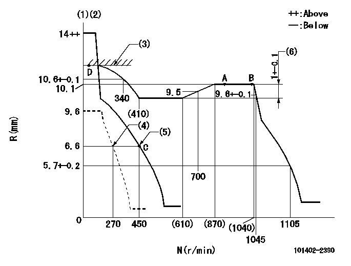
N:Pump speed
R:Rack position (mm)
(1)Target notch: K
(2)Tolerance for racks not indicated: +-0.05mm.
(3)RACK LIMIT
(4)Set idle sub-spring
(5)Main spring setting
(6)Rack difference between N = N1 and N = N2
----------
K=12 N1=900r/min N2=500r/min
----------
----------
K=12 N1=900r/min N2=500r/min
----------
Speed control lever angle
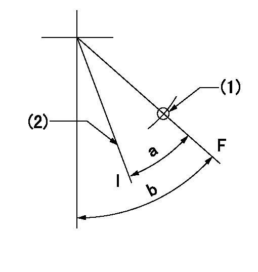
F:Full speed
I:Idle
(1)Use the hole at R = aa
(2)Stopper bolt setting
----------
aa=80mm
----------
a=30deg+-5deg b=56deg+-5deg
----------
aa=80mm
----------
a=30deg+-5deg b=56deg+-5deg
Stop lever angle
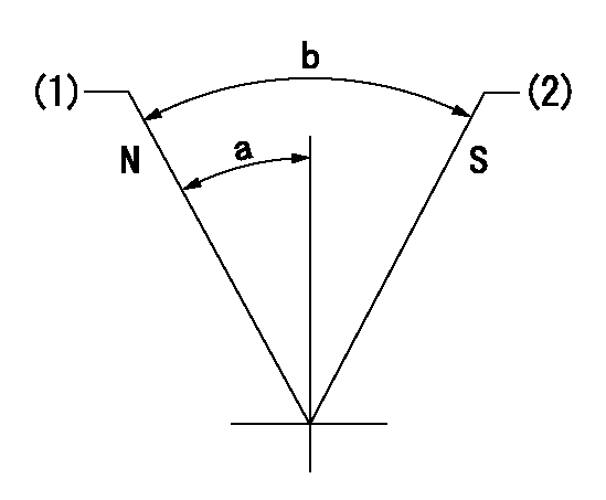
N:Pump normal
S:Stop the pump.
(1)Normal
(2)Rack position aa or less, pump speed bb
----------
aa=6.1mm bb=0r/min
----------
a=27deg+-5deg b=53deg+-5deg
----------
aa=6.1mm bb=0r/min
----------
a=27deg+-5deg b=53deg+-5deg
Timing setting

(1)Pump vertical direction
(2)Position of gear's standard threaded hole at No 1 cylinder's beginning of injection
(3)-
(4)-
----------
----------
a=(70deg)
----------
----------
a=(70deg)
Information:
2. Remove the two bolts (1) from transfer pump, and pull the pump out of accessory drive housing.3. Remove the four bolts and lock from retainer (3). Remove the retainer.4. Remove the drive gear (2). 5. Remove the two bolts, locks, and plate (5).6. Remove the variable timing unit (4) from the accessory drive housing.Install Variable Timing Unit
1. Put the variable timing unit (1) in position in the accessory drive housing.2. Install the retaining plate, locks, and two bolts.3. Install the drive gear, retainer, lock, and four bolts. Do not tighten the four bolts.4. Make an adjustment to the timing of the camshaft for the fuel injection pump. See FUEL INJECTION PUMP CAMSHAFT TIMING in TESTING AND ADJUSTING. 5. Install the cover (4) on timing gear housing.6. Put the transfer pump (3) in position on the accessory drive housing, and install the two bolts (2).7. Check to be sure all timing pins and bolts have been removed from their timing holes, and are installed in their storage positions.Disassemble Variable Timing Unit
start by: a) remove variable timing unit 1. Push down on retainer (1), and remove the pin (2).2. Remove the retainer and spring. 3. Use a hammer and punch to remove the dowels (4). Remove the two weights.4. Remove the piston and rod assembly (5) from shaft assembly (3).5. Remove the pins from nut and rod.6. Remove the rod, nut, spring, and valve from the piston assembly.Assemble Variable Timing Unit
1. Install the valve, spring, and nut on the piston assembly. Turn the nut until the distance (X) between bottom face of nut and the piston is 1.760 in. (44.7 mm). Drill a .095 .002 in. (2.41 0.05 mm) diameter hole through the nut and the threads of piston assembly. Install the pin in nut. 1. Install the rod tight against the nut. Take a measurement .156 in. (3.96 mm) from top face of nut, and put a mark at this location on rod. Drill a .095 .0.05 mm) diameter hole (1) through the rod and piston assembly at this location. Install the pin in rod.3. Install the piston and rod assembly in the shaft assembly. Install the spring, retainer, and pin in shaft assembly.4. Install the weights and dowels. Use a hammer and punch to fasten both ends of the dowels in place. Both weights must move freely after the dowels have been fastened in place.end by: a) install variable timing unit