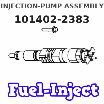
Information injection-pump assembly
BOSCH
F 019 Z20 415
f019z20415
ZEXEL
101402-2383
1014022383
HINO
220206520B
220206520b

Rating:
Service parts 101402-2383 INJECTION-PUMP ASSEMBLY:
1.
_
5.
AUTOM. ADVANCE MECHANIS
6.
COUPLING PLATE
8.
_
9.
_
11.
Nozzle and Holder
236003520A
12.
Open Pre:MPa(Kqf/cm2)
21.6(220)
15.
NOZZLE SET
Cross reference number
Zexel num
Bosch num
Firm num
Name
F 019 Z20 415
220206520B HINO
INJECTION-PUMP ASSEMBLY
W04D-T * K 14BD INJECTION PUMP ASSY PE4AD PE
W04D-T * K 14BD INJECTION PUMP ASSY PE4AD PE
Information:
2. Remove the bolts (1) and water lines (2).3. Loosen the drive belts (4).4. Remove the bolts (3) that hold water pump to cylinder block.5. Remove the water pump.Install Water Pump
1. Put the water pump into position on engine, and install the bolts.2. Put the two water lines in position, and install the four bolts.3. Install the drive belts and tighten them to the tension given in OPERATION AND MAINTENANCE GUIDE.4. Fill the cooling system.Disassemble Water Pump
start by: a) remove water pump 1. Remove nut (1) and lock from shaft. Remove the pulley (2) from shaft.2. Remove bolts (3) from housings, and pull the housings (4) and (5) apart.3. Remove the lip-type seal from housing (4).4. Remove the ring for seal from pulley (2). 5. Lift the shaft (6) out of housing (5). 6. Remove cotter pin, nut (10), and washer. Remove the impeller (8).7. Remove bolts (7) and locks, and remove the housing (9) from shaft. 8. Remove seals (11) and (12) from housing (9).9. Remove the key, two bearings, spacer, and plate from shaft (6).Assemble Water Pump
1. Use tool setup (A) to install the seal in housing (1) with lip of seal toward impeller side of housing. Put oil on lip of seal. 2. Heat the bearings (3) and (6) in oil at a maximum temperature of 275°F (135°C).3. Install bearing (3), plate (4), spacer (5), bearing (6), and key (7) on shaft (2).4. Put housing (1) in position on shaft (2). Install the four bolts (10) and two locks.5. Install the seal and ring in housing (1) with the shiny surface of ring toward impeller. 6. Put the seal assembly in position on shaft, and install the impeller (9). Install washer and nut (8). Tighten the nut to 30 5 lb.ft. (4.1 0.7 mkg) plus amount needed to install the cotter pin.7. Put the shaft, housing, and impeller in position in housing (11). 8. Use tool setup (B) to install seal in housing (13) with lip of seal toward pulley. Install the ring for seal on pulley (15). Put oil on lip of seal.9. Put housing (13) in position, and install the bolts (12). Install pulley (15), lock, and nut (14). Tighten nut to 55 lb.ft. (7.6 mkg) and bend the lock.end by: a) install water pump