Information injection-pump assembly
BOSCH
9 400 612 517
9400612517
ZEXEL
101402-2362
1014022362
HINO
220206102A
220206102a

Rating:
Service parts 101402-2362 INJECTION-PUMP ASSEMBLY:
1.
_
5.
AUTOM. ADVANCE MECHANIS
6.
COUPLING PLATE
8.
_
9.
_
11.
Nozzle and Holder
23600-3420A
12.
Open Pre:MPa(Kqf/cm2)
15.7{160}/21.6{220}
14.
NOZZLE
Cross reference number
BOSCH
9 400 612 517
9400612517
ZEXEL
101402-2362
1014022362
HINO
220206102A
220206102a
Zexel num
Bosch num
Firm num
Name
101402-2362
9 400 612 517
220206102A HINO
INJECTION-PUMP ASSEMBLY
W04D K 14BD INJECTION PUMP ASSY PE4AD PE
W04D K 14BD INJECTION PUMP ASSY PE4AD PE
Calibration Data:
Adjustment conditions
Test oil
1404 Test oil ISO4113 or {SAEJ967d}
1404 Test oil ISO4113 or {SAEJ967d}
Test oil temperature
degC
40
40
45
Nozzle and nozzle holder
105780-8140
Bosch type code
EF8511/9A
Nozzle
105780-0000
Bosch type code
DN12SD12T
Nozzle holder
105780-2080
Bosch type code
EF8511/9
Opening pressure
MPa
17.2
Opening pressure
kgf/cm2
175
Injection pipe
Outer diameter - inner diameter - length (mm) mm 6-2-600
Outer diameter - inner diameter - length (mm) mm 6-2-600
Overflow valve
131424-5720
Overflow valve opening pressure
kPa
255
221
289
Overflow valve opening pressure
kgf/cm2
2.6
2.25
2.95
Tester oil delivery pressure
kPa
255
255
255
Tester oil delivery pressure
kgf/cm2
2.6
2.6
2.6
Direction of rotation (viewed from drive side)
Right R
Right R
Injection timing adjustment
Direction of rotation (viewed from drive side)
Right R
Right R
Injection order
1-3-4-2
Pre-stroke
mm
4.8
4.75
4.85
Beginning of injection position
Drive side NO.1
Drive side NO.1
Difference between angles 1
Cal 1-3 deg. 90 89.5 90.5
Cal 1-3 deg. 90 89.5 90.5
Difference between angles 2
Cal 1-4 deg. 180 179.5 180.5
Cal 1-4 deg. 180 179.5 180.5
Difference between angles 3
Cyl.1-2 deg. 270 269.5 270.5
Cyl.1-2 deg. 270 269.5 270.5
Injection quantity adjustment
Adjusting point
A
Rack position
10.8
Pump speed
r/min
900
900
900
Average injection quantity
mm3/st.
83
81
85
Max. variation between cylinders
%
0
-3
3
Basic
*
Fixing the lever
*
Injection quantity adjustment_02
Adjusting point
-
Rack position
7.5+-0.5
Pump speed
r/min
400
400
400
Average injection quantity
mm3/st.
11.5
10
13
Max. variation between cylinders
%
0
-15
15
Fixing the rack
*
Remarks
Adjust only variation between cylinders; adjust governor according to governor specifications.
Adjust only variation between cylinders; adjust governor according to governor specifications.
Injection quantity adjustment_03
Adjusting point
D
Rack position
11++
Pump speed
r/min
100
100
100
Average injection quantity
mm3/st.
90
90
100
Fixing the lever
*
Rack limit
*
Test data Ex:
Governor adjustment
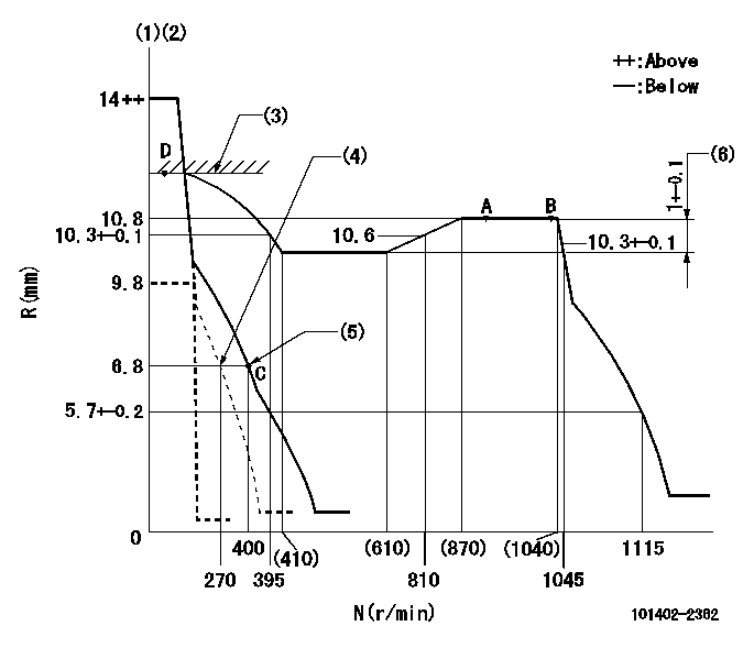
N:Pump speed
R:Rack position (mm)
(1)Target notch: K
(2)Tolerance for racks not indicated: +-0.05mm.
(3)RACK LIMIT
(4)Set idle sub-spring
(5)Main spring setting
(6)Rack difference between N = N1 and N = N2
----------
K=12 N1=900r/min N2=500r/min
----------
----------
K=12 N1=900r/min N2=500r/min
----------
Speed control lever angle
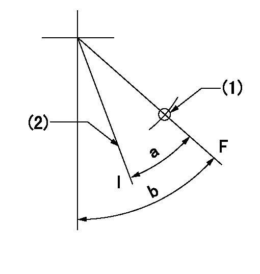
F:Full speed
I:Idle
(1)Use the hole at R = aa
(2)Stopper bolt setting
----------
aa=80mm
----------
a=26deg+-5deg b=52deg+-5deg
----------
aa=80mm
----------
a=26deg+-5deg b=52deg+-5deg
Stop lever angle
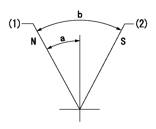
N:Pump normal
S:Stop the pump.
(1)Normal
(2)Rack position aa or less, pump speed bb
----------
aa=6.3mm bb=0r/min
----------
a=27deg+-5deg b=53deg+-5deg
----------
aa=6.3mm bb=0r/min
----------
a=27deg+-5deg b=53deg+-5deg
Timing setting

(1)Pump vertical direction
(2)Position of gear's standard threaded hole at No 1 cylinder's beginning of injection
(3)-
(4)-
----------
----------
a=(70deg)
----------
----------
a=(70deg)
Information:
PROBLEM
The existing fuel injectors can experience injector failures due to injector body cracking. If the existing injector fails it can result in complaints of high oil levels due to excessive fuel dilution.
AFFECTED PRODUCT
Model Identification Number
C27 A6X00101-00105
EGG00100
NAR00100-00119
T4Z00100, 200-227, 236
C32 NST00100-00108
SDK00101-00198
PMC27 N1B00100-00105, 107-118, 120-126, 128
PARTS NEEDED
Qty
Part Number Description
2 1R1808 FILTER-LUBE
12 8S9191 BOLT
12 3594060 INJECTOR GP-FUEL
1 BULK_OIL DEO (Refer to the OMM for Refill Capacities)
In order to allow equitable parts availability to all participating dealers, please limit your initial parts order to not exceed 2% of dealership population. This is an initial order recommendation only, and the ultimate responsibility for ordering the total number of parts needed to satisfy the program lies with the dealer.
ACTION REQUIRED
If excessive fuel dilution of engine oil is found reference the following to determine the cause of fuel dilution.
Refer to Special Instruction, REHS3007, "Determining the Cause of Fuel Dilution of Engine Oil"
Troubleshooting C27 and C32 Engines:
UENR0505 C27 Petroleum Generator Set Engines
UENR0504 C27 and C32 Industrial Engines
KENR9192 C27 Generator Set Engines
Once an injector(s) has been identified as having a cracked/leaking injector body, replace the failed injector(s). Inspect the remaining good injector serial numbers with Cat ET, (Injector Serial Numbers = Injector trim file name, (ie 6Cxxxxxxxxxx.trm)). If the remaining injector serial numbers fall within the serial number range below, replace at the same time. Refer to Image 1 for the serial number location on the top of the electronic unit injector.
Injector Serial Numbers
6C001793971D through 6C002198297C
8S-9191 Injector Hold Down Bolt must be replaced.
Refer to Disassembly and Assembly, KENR8167 for the removal, installation, and tightening procedures.
After the engine is reassembled, change the engine oil and filters.
Image1
SERVICE CLAIM ALLOWANCES
Product smu/age whichever comes first Caterpillar Dealer Suggested Customer Suggested
Parts % Labor Hrs% Parts % Labor Hrs% Parts % Labor Hrs%
0-3500 hrs,
0-24 mo 100.0% 100.0% 0.0% 0.0% 0.0% 0.0%
3501-6000 hrs,
25-48 mo 50.0% 50.0% 0.0% 0.0% 50.0% 50.0%
This is a 10.0-hour job
If there has been a previous repair, part age/hours will apply. Retain a copy of the previous repair invoice in the dealer's records for audit purposes, and specify repair date and machine hours in the "Additional Comments" section of the warranty claim.
PARTS DISPOSITION
Handle the parts in accordance with your Warranty Bulletin on warranty parts handling.
Have questions with 101402-2362?
Group cross 101402-2362 ZEXEL
Hino
Hino
Hino
Hino
101402-2362
9 400 612 517
220206102A
INJECTION-PUMP ASSEMBLY
W04D
W04D