Information injection-pump assembly
BOSCH
9 400 612 448
9400612448
ZEXEL
101402-2333
1014022333
HINO
220205312A
220205312a
Rating:
Service parts 101402-2333 INJECTION-PUMP ASSEMBLY:
1.
_
5.
AUTOM. ADVANCE MECHANIS
6.
COUPLING PLATE
8.
_
9.
_
11.
Nozzle and Holder
23600-2150
12.
Open Pre:MPa(Kqf/cm2)
21.6{220}
15.
NOZZLE SET
Cross reference number
BOSCH
9 400 612 448
9400612448
ZEXEL
101402-2333
1014022333
HINO
220205312A
220205312a
Zexel num
Bosch num
Firm num
Name
9 400 612 448
220205312A HINO
INJECTION-PUMP ASSEMBLY
W04C-TI * K 14BC PE4A,5A, PE
W04C-TI * K 14BC PE4A,5A, PE
Calibration Data:
Adjustment conditions
Test oil
1404 Test oil ISO4113 or {SAEJ967d}
1404 Test oil ISO4113 or {SAEJ967d}
Test oil temperature
degC
40
40
45
Nozzle and nozzle holder
105780-8140
Bosch type code
EF8511/9A
Nozzle
105780-0000
Bosch type code
DN12SD12T
Nozzle holder
105780-2080
Bosch type code
EF8511/9
Opening pressure
MPa
17.2
Opening pressure
kgf/cm2
175
Injection pipe
Outer diameter - inner diameter - length (mm) mm 6-2-600
Outer diameter - inner diameter - length (mm) mm 6-2-600
Overflow valve
131424-5720
Overflow valve opening pressure
kPa
255
221
289
Overflow valve opening pressure
kgf/cm2
2.6
2.25
2.95
Tester oil delivery pressure
kPa
157
157
157
Tester oil delivery pressure
kgf/cm2
1.6
1.6
1.6
Direction of rotation (viewed from drive side)
Right R
Right R
Injection timing adjustment
Direction of rotation (viewed from drive side)
Right R
Right R
Injection order
1-3-4-2
Pre-stroke
mm
3.2
3.17
3.23
Beginning of injection position
Drive side NO.1
Drive side NO.1
Difference between angles 1
Cal 1-3 deg. 90 89.75 90.25
Cal 1-3 deg. 90 89.75 90.25
Difference between angles 2
Cal 1-4 deg. 180 179.75 180.25
Cal 1-4 deg. 180 179.75 180.25
Difference between angles 3
Cyl.1-2 deg. 270 269.75 270.25
Cyl.1-2 deg. 270 269.75 270.25
Injection quantity adjustment
Adjusting point
A
Rack position
9.8
Pump speed
r/min
1600
1600
1600
Average injection quantity
mm3/st.
103
101
105
Max. variation between cylinders
%
0
-3
3
Basic
*
Fixing the lever
*
Boost pressure
kPa
40
40
Boost pressure
mmHg
300
300
Injection quantity adjustment_02
Adjusting point
B
Rack position
7+-0.5
Pump speed
r/min
260
260
260
Average injection quantity
mm3/st.
9.5
8
11
Max. variation between cylinders
%
0
-15
15
Fixing the rack
*
Boost pressure
kPa
0
0
0
Boost pressure
mmHg
0
0
0
Injection quantity adjustment_03
Adjusting point
C
Rack position
R1(8.8)
Pump speed
r/min
600
600
600
Average injection quantity
mm3/st.
62.5
60.5
64.5
Fixing the lever
*
Boost pressure
kPa
0
0
0
Boost pressure
mmHg
0
0
0
Boost compensator adjustment
Pump speed
r/min
600
600
600
Rack position
R1(8.8)
Boost pressure
kPa
14.7
12
17.4
Boost pressure
mmHg
110
90
130
Boost compensator adjustment_02
Pump speed
r/min
600
600
600
Rack position
(9.8)
Boost pressure
kPa
26.7
26.7
26.7
Boost pressure
mmHg
200
200
200
Test data Ex:
Governor adjustment
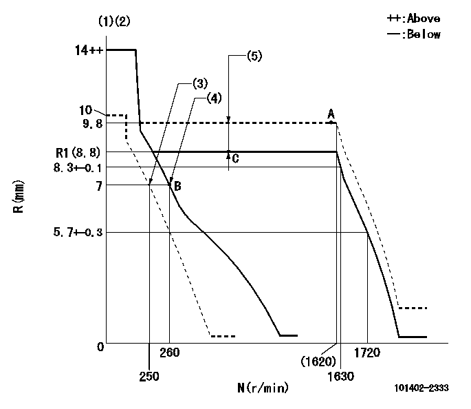
N:Pump speed
R:Rack position (mm)
(1)Target notch: K
(2)Tolerance for racks not indicated: +-0.05mm.
(3)Set idle sub-spring
(4)Main spring setting
(5)Boost compensator stroke: BCL
----------
K=11 BCL=(1)mm
----------
----------
K=11 BCL=(1)mm
----------
Speed control lever angle

F:Full speed
I:Idle
(1)Stopper bolt setting
----------
----------
a=20deg+-5deg b=29deg+-5deg
----------
----------
a=20deg+-5deg b=29deg+-5deg
Stop lever angle

N:Pump normal
S:Stop the pump.
(1)Pump speed aa and rack position bb (to be sealed at delivery)
----------
aa=0r/min bb=1-0.5mm
----------
a=21deg+-5deg b=(55deg)
----------
aa=0r/min bb=1-0.5mm
----------
a=21deg+-5deg b=(55deg)
Timing setting

(1)Pump vertical direction
(2)Position of gear's standard threaded hole at No 1 cylinder's beginning of injection
(3)-
(4)-
----------
----------
a=(70deg)
----------
----------
a=(70deg)
Information:
An additional 0.6 hours labor will be allowed per injector replaced due to inspection results.
On twin engine vessels, include the serial number of the sister engine in the claim story.
Product smu/age whichever comes first Caterpillar Dealer Suggested Customer Suggested
Parts % Labor Hrs% Parts % Labor Hrs% Parts % Labor Hrs%
*******Group 2*******
0-3000 hrs,
0-36 mo 100.0% 100.0% 0.0% 0.0% 0.0% 0.0%
This is a 3.0-hour job for Group 2
An additional 0.6 hours labor will be allowed per injector replaced due to inspection results.
On twin engine vessels, include the serial number of the sister engine in the claim story.
Product smu/age whichever comes first Caterpillar Dealer Suggested Customer Suggested
Parts % Labor Hrs% Parts % Labor Hrs% Parts % Labor Hrs%
*******Group 3*******
0-3000 hrs,
0-36 mo 100.0% 100.0% 0.0% 0.0% 0.0% 0.0%
This is a 2.6-hour job for Group 3
An additional 0.6 hours labor will be allowed per injector replaced due to inspection results.
On twin engine vessels, include the serial number of the sister engine in the claim story.
Product smu/age whichever comes first Caterpillar Dealer Suggested Customer Suggested
Parts % Labor Hrs% Parts % Labor Hrs% Parts % Labor Hrs%
*******Group 4*******
0-3000 hrs,
0-36 mo 100.0% 100.0% 0.0% 0.0% 0.0% 0.0%
This is a 3.0-hour job for Group 4
An additional 0.6 hours labor will be allowed per injector replaced due to inspection results.
On twin engine vessels, include the serial number of the sister engine in the claim story.
PARTS DISPOSITION
Handle the parts in accordance with your Warranty Bulletin on warranty parts handling.