Information injection-pump assembly
BOSCH
F 019 Z10 572
f019z10572
ZEXEL
101402-2310
1014022310
HINO
220204970A
220204970a
Rating:
Service parts 101402-2310 INJECTION-PUMP ASSEMBLY:
1.
_
5.
AUTOM. ADVANCE MECHANIS
6.
COUPLING PLATE
8.
_
9.
_
11.
Nozzle and Holder
12.
Open Pre:MPa(Kqf/cm2)
21.6(220)
15.
NOZZLE SET
Cross reference number
BOSCH
F 019 Z10 572
f019z10572
ZEXEL
101402-2310
1014022310
HINO
220204970A
220204970a
Zexel num
Bosch num
Firm num
Name
Calibration Data:
Adjustment conditions
Test oil
1404 Test oil ISO4113 or {SAEJ967d}
1404 Test oil ISO4113 or {SAEJ967d}
Test oil temperature
degC
40
40
45
Nozzle and nozzle holder
105780-8140
Bosch type code
EF8511/9A
Nozzle
105780-0000
Bosch type code
DN12SD12T
Nozzle holder
105780-2080
Bosch type code
EF8511/9
Opening pressure
MPa
17.2
Opening pressure
kgf/cm2
175
Injection pipe
Outer diameter - inner diameter - length (mm) mm 6-2-600
Outer diameter - inner diameter - length (mm) mm 6-2-600
Overflow valve
134424-0920
Overflow valve opening pressure
kPa
162
147
177
Overflow valve opening pressure
kgf/cm2
1.65
1.5
1.8
Tester oil delivery pressure
kPa
157
157
157
Tester oil delivery pressure
kgf/cm2
1.6
1.6
1.6
Direction of rotation (viewed from drive side)
Right R
Right R
Injection timing adjustment
Direction of rotation (viewed from drive side)
Right R
Right R
Injection order
1-3-4-2
Pre-stroke
mm
3.2
3.17
3.23
Beginning of injection position
Drive side NO.1
Drive side NO.1
Difference between angles 1
Cal 1-3 deg. 90 89.75 90.25
Cal 1-3 deg. 90 89.75 90.25
Difference between angles 2
Cal 1-4 deg. 180 179.75 180.25
Cal 1-4 deg. 180 179.75 180.25
Difference between angles 3
Cyl.1-2 deg. 270 269.75 270.25
Cyl.1-2 deg. 270 269.75 270.25
Injection quantity adjustment
Adjusting point
A
Rack position
9.5
Pump speed
r/min
1600
1600
1600
Average injection quantity
mm3/st.
85.5
83.5
87.5
Max. variation between cylinders
%
0
-3
3
Basic
*
Fixing the lever
*
Injection quantity adjustment_02
Adjusting point
B
Rack position
7.4+-0.5
Pump speed
r/min
280
280
280
Average injection quantity
mm3/st.
11.5
10
13
Max. variation between cylinders
%
0
-15
15
Fixing the rack
*
Test data Ex:
Governor adjustment
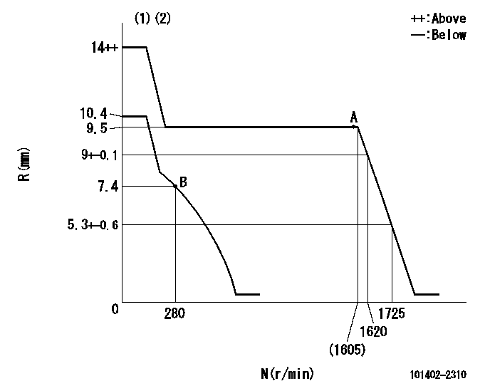
N:Pump speed
R:Rack position (mm)
(1)Target notch: K
(2)Tolerance for racks not indicated: +-0.05mm.
----------
K=9
----------
----------
K=9
----------
Speed control lever angle

F:Full speed
I:Idle
(1)Stopper bolt setting
----------
----------
a=17deg+-5deg b=30deg+-5deg
----------
----------
a=17deg+-5deg b=30deg+-5deg
Stop lever angle

N:Pump normal
S:Stop the pump.
(1)Rack position aa or less, pump speed bb
----------
aa=6.9mm bb=0r/min
----------
a=27deg+-5deg b=53deg+-5deg
----------
aa=6.9mm bb=0r/min
----------
a=27deg+-5deg b=53deg+-5deg
Timing setting

(1)Pump vertical direction
(2)Position of gear's standard threaded hole at No 1 cylinder's beginning of injection
(3)-
(4)-
----------
----------
a=(70deg)
----------
----------
a=(70deg)
Information:
This Revised Service Letter replaces the 20Nov2008 Service Letter. Changes have been made to Parts Needed Description.
TERMINATION DATE
30Nov2010
PROBLEM
The existing governor linkage can separate at the riveted joint on certain C1.6 engines. If the existing governor linkage fails, it can result in loss of engine speed governing.
AFFECTED PRODUCT
Model Identification Number
C1.6 C1M00596-00703, 740-883
PARTS NEEDED
Qty
Part Number Description
1 2152619 GASKET
1 2908469 LEVER AS
1 2952235 GASKET
In order to allow equitable parts availability to all participating dealers, please limit your initial parts order to not exceed 9% of dealership population. This is an initial order recommendation only, and the ultimate responsibility for ordering the total number of parts needed to satisfy the program lies with the dealer.
ACTION REQUIRED
Gain access to engine front cover and fuel pump. Replace the existing governor linkage using the following steps.
Refer to service manual module RENR2424.
Refer to the attached Rework Procedure.
SERVICE CLAIM ALLOWANCES
Product smu/age whichever comes first Caterpillar Dealer Suggested Customer Suggested
Parts % Labor Hrs% Parts % Labor Hrs% Parts % Labor Hrs%
0-2000 hrs,
0-24 mo 100.0% 100.0% 0.0% 0.0% 0.0% 0.0%
This is a 8.0-hour job
PARTS DISPOSITION
Handle the parts in accordance with your Warranty Bulletin on warranty parts handling.
Rework Procedure
Refer to service manual module RENR2424.
1. Remove fuel injection pump. Refer to SMCS 1251-011 (Fuel Injection Pump-Remove).
2. Remove crankshaft pulley. Refer to SMCS 1205-010 (Crankshaft Pulley-Remove and Install).
3. Remove engine front cover. Refer to SMCS 1151-011 (Housing (Front) Remove).
4. Remove fuel injection pump linkage from housing. Refer to SMCS 1151-015 (Housing (Front)-Disassemble).
5. Install new 290-8469 fuel injection pump linkage. Refer to 'Installation of fuel injection pump linkage' within SMCS 1151-016 (Housing (Front)-Assemble).
6. Install engine front cover with new gasket. Refer to SMCS 1151-012 (Housing (Front)-Install).
7. Install crankshaft pulley. Refer to SMCS 1205-010 (Crankshaft Pulley - Remove and Install).
8. Install fuel injection pump. Refer to SMCS 1251-012 (Fuel Injection Pump - Install).
9. Run engine to ensure correct operation. Check for any signs of leaks.
10. Check low and high idle, and reset appropriately.
11. Refit any machine parts that were removed to gain access to engine front cover and fuel pump.