Information injection-pump assembly
BOSCH
9 400 610 438
9400610438
ZEXEL
101402-2301
1014022301
HINO
220204961A
220204961a
Rating:
Service parts 101402-2301 INJECTION-PUMP ASSEMBLY:
1.
_
5.
AUTOM. ADVANCE MECHANIS
6.
COUPLING PLATE
8.
_
9.
_
11.
Nozzle and Holder
23600-1710A
12.
Open Pre:MPa(Kqf/cm2)
21.6{220}
15.
NOZZLE SET
Cross reference number
BOSCH
9 400 610 438
9400610438
ZEXEL
101402-2301
1014022301
HINO
220204961A
220204961a
Zexel num
Bosch num
Firm num
Name
101402-2301
9 400 610 438
220204961A HINO
INJECTION-PUMP ASSEMBLY
W04C-T K 14BC INJECTION PUMP ASSY PE4A,5A, PE
W04C-T K 14BC INJECTION PUMP ASSY PE4A,5A, PE
Calibration Data:
Adjustment conditions
Test oil
1404 Test oil ISO4113 or {SAEJ967d}
1404 Test oil ISO4113 or {SAEJ967d}
Test oil temperature
degC
40
40
45
Nozzle and nozzle holder
105780-8140
Bosch type code
EF8511/9A
Nozzle
105780-0000
Bosch type code
DN12SD12T
Nozzle holder
105780-2080
Bosch type code
EF8511/9
Opening pressure
MPa
17.2
Opening pressure
kgf/cm2
175
Injection pipe
Outer diameter - inner diameter - length (mm) mm 6-2-600
Outer diameter - inner diameter - length (mm) mm 6-2-600
Overflow valve
134424-0920
Overflow valve opening pressure
kPa
162
147
177
Overflow valve opening pressure
kgf/cm2
1.65
1.5
1.8
Tester oil delivery pressure
kPa
157
157
157
Tester oil delivery pressure
kgf/cm2
1.6
1.6
1.6
Direction of rotation (viewed from drive side)
Right R
Right R
Injection timing adjustment
Direction of rotation (viewed from drive side)
Right R
Right R
Injection order
1-3-4-2
Pre-stroke
mm
3.2
3.17
3.23
Beginning of injection position
Drive side NO.1
Drive side NO.1
Difference between angles 1
Cal 1-3 deg. 90 89.75 90.25
Cal 1-3 deg. 90 89.75 90.25
Difference between angles 2
Cal 1-4 deg. 180 179.75 180.25
Cal 1-4 deg. 180 179.75 180.25
Difference between angles 3
Cyl.1-2 deg. 270 269.75 270.25
Cyl.1-2 deg. 270 269.75 270.25
Injection quantity adjustment
Adjusting point
A
Rack position
9.9
Pump speed
r/min
1600
1600
1600
Average injection quantity
mm3/st.
90
88
92
Max. variation between cylinders
%
0
-3
3
Basic
*
Fixing the lever
*
Injection quantity adjustment_02
Adjusting point
B
Rack position
7.3+-0.5
Pump speed
r/min
280
280
280
Average injection quantity
mm3/st.
11.5
10
13
Max. variation between cylinders
%
0
-15
15
Fixing the rack
*
Test data Ex:
Governor adjustment
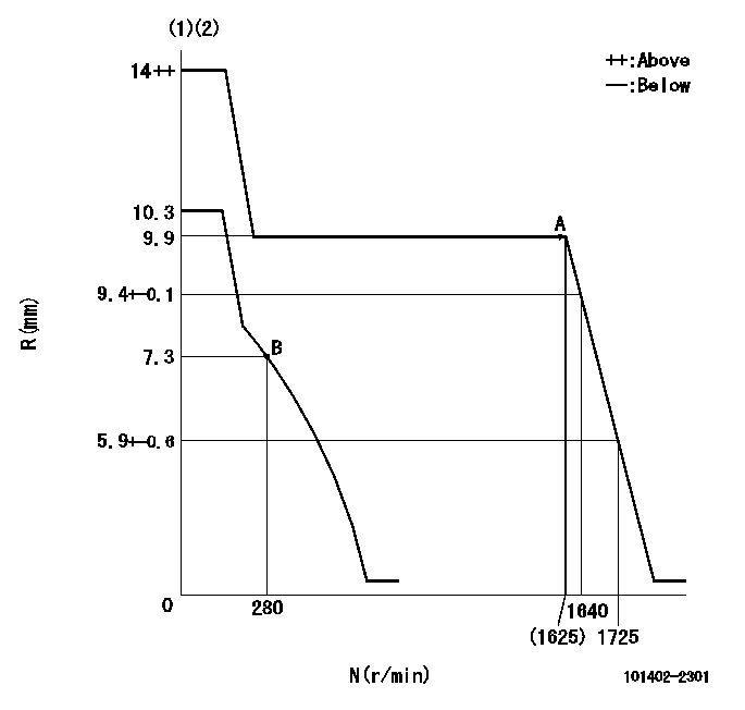
N:Pump speed
R:Rack position (mm)
(1)Target notch: K
(2)Tolerance for racks not indicated: +-0.05mm.
----------
K=10
----------
----------
K=10
----------
Speed control lever angle

F:Full speed
I:Idle
(1)Stopper bolt setting
----------
----------
a=17deg+-5deg b=30deg+-5deg
----------
----------
a=17deg+-5deg b=30deg+-5deg
Stop lever angle

N:Pump normal
S:Stop the pump.
(1)Rack position aa or less, pump speed bb
----------
aa=6.8mm bb=0r/min
----------
a=27deg+-5deg b=53deg+-5deg
----------
aa=6.8mm bb=0r/min
----------
a=27deg+-5deg b=53deg+-5deg
Timing setting

(1)Pump vertical direction
(2)Position of gear's standard threaded hole at No 1 cylinder's beginning of injection
(3)-
(4)-
----------
----------
a=(70deg)
----------
----------
a=(70deg)
Information:
This Program can only be administered after a failure occurs.The decision whether to apply the Program is made by the dealer. When reporting the repair, use "PS51584" as the Part Numberand "7755" as the Group Number. Use "96" as the Warranty Claim Description Code and use "Z" as the SIMS Description Code.
The information supplied in this service letter may not be valid after the termination date of this program.Do not perform the work outlined in this Service Letter after the termination date without first contacting your Caterpillar product analyst.
TERMINATION DATE
30Nov2010
PROBLEM
The existing fuel injector can fail on certain C32 Marine Engines. If the existing fuel injector fails it will cause a dead injector resulting in no fuel being delivered to cylinder.
AFFECTED PRODUCT
Model Identification Number
C32 RNC02662, 2722, 2726, 2731-2735, 2737-2747, 2749-2759, 2762-2766, 2768-2770, 2772, 2778, 2782, 2787-2788, 2791-2796, 2798, 2800-2818, 2820-2824, 2826-2834, 2836, 2839-2854, 2856-2866, 2868-2878, 2880-2883, 2885-2888, 2892-2895, 2897-2903, 2905-2906, 2908-2910, 2912-2918, 2920-2933, 2935-2936, 2938-2939, 2941, 2944-2947, 2949-2952, 2954-2963, 2965, 2969-2971, 2973-2986, 2988, 2990-3009, 3014-3035, 3037-3039, 3041-3127, 3129-3134, 3136, 3139, 3142-3172, 3174, 3177-3197
RND00101-00103, 114, 123-124, 132-133, 136-146, 151, 159-160, 192-194, 202, 204, 207, 210, 221, 228-249, 251, 253-254, 256-257, 263, 266-267, 270-271, 274-275, 277
RNE00102-00103, 106-111, 114-116, 118-119, 121, 124
RNR00100-00101, 103, 105-107, 109-110, 112-113, 115
T3T00101-00104, 106-110, 112-123, 128, 137-144, 147-148, 190
PARTS NEEDED
Qty
Part Number Description
12 2768307 INJECTOR GP-FUEL
In order to allow equitable parts availability to all participating dealers, please limit your initial parts order to not exceed 3% of dealership population. This is an initial order recommendation only, and the ultimate responsibility for ordering the total number of parts needed to satisfy the program lies with the dealer.
ACTION REQUIRED
After failures of a single injector, replace all 12. See RENR8628 for Disassembly and Assembly instructions.
SERVICE CLAIM ALLOWANCES
Product smu/age whichever comes first Caterpillar Dealer Suggested Customer Suggested
Parts % Labor Hrs% Parts % Labor Hrs% Parts % Labor Hrs%
0-100 hrs 100.0% 100.0% 0.0% 0.0% 0.0% 0.0%
This is a 11.0-hour job
PARTS DISPOSITION
Handle the parts in accordance with your Warranty Bulletin on warranty parts handling.
Have questions with 101402-2301?
Group cross 101402-2301 ZEXEL
Hino
101402-2301
9 400 610 438
220204961A
INJECTION-PUMP ASSEMBLY
W04C-T
W04C-T