Information injection-pump assembly
BOSCH
F 019 Z10 571
f019z10571
ZEXEL
101402-2300
1014022300
HINO
220204960A
220204960a
Rating:
Service parts 101402-2300 INJECTION-PUMP ASSEMBLY:
1.
_
5.
AUTOM. ADVANCE MECHANIS
6.
COUPLING PLATE
8.
_
9.
_
11.
Nozzle and Holder
12.
Open Pre:MPa(Kqf/cm2)
21.6(220)
15.
NOZZLE SET
Cross reference number
BOSCH
F 019 Z10 571
f019z10571
ZEXEL
101402-2300
1014022300
HINO
220204960A
220204960a
Zexel num
Bosch num
Firm num
Name
Calibration Data:
Adjustment conditions
Test oil
1404 Test oil ISO4113 or {SAEJ967d}
1404 Test oil ISO4113 or {SAEJ967d}
Test oil temperature
degC
40
40
45
Nozzle and nozzle holder
105780-8140
Bosch type code
EF8511/9A
Nozzle
105780-0000
Bosch type code
DN12SD12T
Nozzle holder
105780-2080
Bosch type code
EF8511/9
Opening pressure
MPa
17.2
Opening pressure
kgf/cm2
175
Injection pipe
Outer diameter - inner diameter - length (mm) mm 6-2-600
Outer diameter - inner diameter - length (mm) mm 6-2-600
Overflow valve
134424-0920
Overflow valve opening pressure
kPa
162
147
177
Overflow valve opening pressure
kgf/cm2
1.65
1.5
1.8
Tester oil delivery pressure
kPa
157
157
157
Tester oil delivery pressure
kgf/cm2
1.6
1.6
1.6
Direction of rotation (viewed from drive side)
Right R
Right R
Injection timing adjustment
Direction of rotation (viewed from drive side)
Right R
Right R
Injection order
1-3-4-2
Pre-stroke
mm
3.2
3.17
3.23
Beginning of injection position
Drive side NO.1
Drive side NO.1
Difference between angles 1
Cal 1-3 deg. 90 89.75 90.25
Cal 1-3 deg. 90 89.75 90.25
Difference between angles 2
Cal 1-4 deg. 180 179.75 180.25
Cal 1-4 deg. 180 179.75 180.25
Difference between angles 3
Cyl.1-2 deg. 270 269.75 270.25
Cyl.1-2 deg. 270 269.75 270.25
Injection quantity adjustment
Adjusting point
A
Rack position
9.7
Pump speed
r/min
1600
1600
1600
Average injection quantity
mm3/st.
89
87
91
Max. variation between cylinders
%
0
-3
3
Basic
*
Fixing the lever
*
Injection quantity adjustment_02
Adjusting point
B
Rack position
7.4+-0.5
Pump speed
r/min
280
280
280
Average injection quantity
mm3/st.
11.5
10
13
Max. variation between cylinders
%
0
-15
15
Fixing the rack
*
Test data Ex:
Governor adjustment
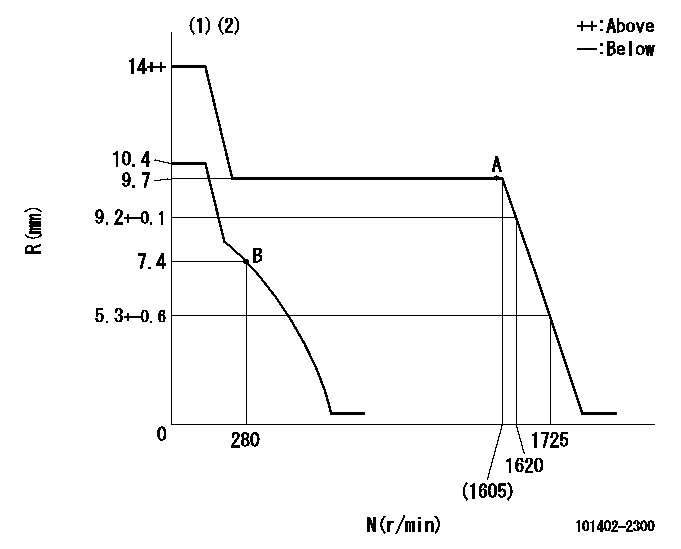
N:Pump speed
R:Rack position (mm)
(1)Target notch: K
(2)Tolerance for racks not indicated: +-0.05mm.
----------
K=8
----------
----------
K=8
----------
Speed control lever angle

F:Full speed
I:Idle
(1)Stopper bolt setting
----------
----------
a=16deg+-5deg b=30deg+-5deg
----------
----------
a=16deg+-5deg b=30deg+-5deg
Stop lever angle

N:Pump normal
S:Stop the pump.
(1)Rack position aa or less, pump speed bb
----------
aa=6.9mm bb=0r/min
----------
a=27deg+-5deg b=53deg+-5deg
----------
aa=6.9mm bb=0r/min
----------
a=27deg+-5deg b=53deg+-5deg
Timing setting

(1)Pump vertical direction
(2)Position of gear's standard threaded hole at No 1 cylinder's beginning of injection
(3)-
(4)-
----------
----------
a=(70deg)
----------
----------
a=(70deg)
Information:
ACTION REQUIRED
Check Plug Replacement:
1) Check engine serial number to ensure it is included in the affected rework population.
2) Inspect fuel injection pump outlet check plugs installed on pump. Refer to Image1 for check plug location. If the fuel injection pump outlet check plugs have dimples as shown in Image2 DO NOT perform plug rework.
3) If check plugs do not have dimples as shown in Image2 the plugs need to be replaced, refer to Special Instructions REHS3841 for proper plug installation.
Fuel Line Inspect and Possibly Replace:
Refer to Special Instructions REHS3842 for C7, and REHS3846 for C9. Inspect all high pressure fuel lines that require clamping to ensure proper clamping location and torque for each clamp that holds each high pressure fuel line in place. Verify all rubber grommets are present in each clamp. The fuel line(s) must be replaced if the clamp location/torque and or the grommets are not correct.
Reference line kit part numbers below for C7 and C9 if needed after inspection is complete.
DESCRIPTION______________________KIT
C7
Tube As.-Fuel_(Pump Line)______310-6027
Tube As.-Fuel_(Line 1)_________310-6029
Tube As.-Fuel_(Line 6)_________310-6030
C9
Tube As.-Fuel_(Pump Line)______310-6031
Tube As.-Fuel_(Line 1)_________310-6032
Tube As.-Fuel_(Lines 5 & 6)____310-6033
Image1
Image2
OWNER NOTIFICATION
U.S. and Canadian owners will receive the attached Owner Notification.
SERVICE CLAIM ALLOWANCES
Caterpillar Dealer Suggested Customer Suggested
Parts % Labor Hrs% Parts % Labor Hrs% Parts % Labor Hrs%
100% 100% 0% 0% 0% 0%
This is a 1.0-hour job
Add an additional 0.2 Hrs per high pressure fuel line replaced in step 4 in the Action Required if needed.
PARTS DISPOSITION
Handle the parts in accordance with your Warranty Bulletin on warranty parts handling.
Only return high pressure fuel line(s) replaced during this rework to the address below.
Make sure the outside of the shipping container is marked PIXXXX.
Caterpillar Inc.
Attn: PIXXXXX
Route 29 And Old Galena Road
Building DD, Dock 8,Engineering Parts Return Area
MOSSVILLE, IL 61552
USA
MAKE EVERY EFFORT TO COMPLETE THIS PROGRAM AS SOON AS POSSIBLE.
IMPORTANT: SAFETY
SAFETY ? RECALL FOR REPLACING THE FUEL PUMP PLUGS
MODELS INVOLVED - Certain C7 and C9 Truck and Bus Engines
Dear Caterpillar Product Owner:
This notice is sent to you in accordance with the requirements of the National Traffic and Motor Vehicle Safety Act, and the requirements of the Canadian Motor Vehicle Safety Act. Caterpillar has decided that a defect which relates to motor vehicle safety exists in 2008 and 2009 model year trucks and buses equipped with certain Caterpillar C7 and C9 diesel engines.
A fuel pump plug may crack, which could cause fuel to spray and leak. Fuel in the presence of an ignition source can result in a fire. The driver may also become aware due to decrease in engine power or the illumination of a check engine lamp or engine protection lamp. New fuel pump plugs will be installed on the engine. You will not be charged for the service performed.
Please contact your local Caterpillar dealer immediately to schedule this service. The dealer will advise you of the time required to complete this service.
If you are a lessor of these vehicles, you must forward this letter to your lessee within ten days.
If you have had your vehicle repaired for this concern prior to receipt of this notice and incurred any costs, you may be eligible for