Information injection-pump assembly
BOSCH
9 400 610 437
9400610437
ZEXEL
101402-2290
1014022290
Rating:
Service parts 101402-2290 INJECTION-PUMP ASSEMBLY:
1.
_
5.
AUTOM. ADVANCE MECHANIS
6.
COUPLING PLATE
8.
_
9.
_
11.
Nozzle and Holder
23600-2561A
12.
Open Pre:MPa(Kqf/cm2)
17.7{180}
15.
NOZZLE SET
Cross reference number
BOSCH
9 400 610 437
9400610437
ZEXEL
101402-2290
1014022290
Zexel num
Bosch num
Firm num
Name
Calibration Data:
Adjustment conditions
Test oil
1404 Test oil ISO4113 or {SAEJ967d}
1404 Test oil ISO4113 or {SAEJ967d}
Test oil temperature
degC
40
40
45
Nozzle and nozzle holder
105780-8140
Bosch type code
EF8511/9A
Nozzle
105780-0000
Bosch type code
DN12SD12T
Nozzle holder
105780-2080
Bosch type code
EF8511/9
Opening pressure
MPa
17.2
Opening pressure
kgf/cm2
175
Injection pipe
Outer diameter - inner diameter - length (mm) mm 6-2-600
Outer diameter - inner diameter - length (mm) mm 6-2-600
Overflow valve
134424-0920
Overflow valve opening pressure
kPa
162
147
177
Overflow valve opening pressure
kgf/cm2
1.65
1.5
1.8
Tester oil delivery pressure
kPa
157
157
157
Tester oil delivery pressure
kgf/cm2
1.6
1.6
1.6
Direction of rotation (viewed from drive side)
Right R
Right R
Injection timing adjustment
Direction of rotation (viewed from drive side)
Right R
Right R
Injection order
1-3-4-2
Pre-stroke
mm
3.2
3.17
3.23
Beginning of injection position
Drive side NO.1
Drive side NO.1
Difference between angles 1
Cal 1-3 deg. 90 89.75 90.25
Cal 1-3 deg. 90 89.75 90.25
Difference between angles 2
Cal 1-4 deg. 180 179.75 180.25
Cal 1-4 deg. 180 179.75 180.25
Difference between angles 3
Cyl.1-2 deg. 270 269.75 270.25
Cyl.1-2 deg. 270 269.75 270.25
Injection quantity adjustment
Adjusting point
A
Rack position
10.5
Pump speed
r/min
900
900
900
Average injection quantity
mm3/st.
87
85
89
Max. variation between cylinders
%
0
-3
3
Basic
*
Fixing the lever
*
Injection quantity adjustment_02
Adjusting point
-
Rack position
6.2+-0.5
Pump speed
r/min
375
375
375
Average injection quantity
mm3/st.
8
6.5
9.5
Max. variation between cylinders
%
0
-15
15
Fixing the rack
*
Remarks
Adjust only variation between cylinders; adjust governor according to governor specifications.
Adjust only variation between cylinders; adjust governor according to governor specifications.
Test data Ex:
Governor adjustment
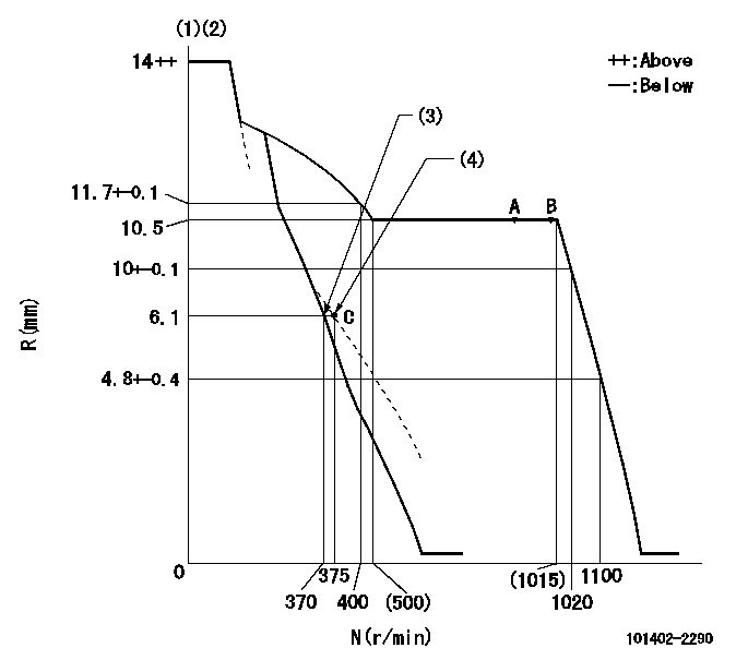
N:Pump speed
R:Rack position (mm)
(1)Target notch: K
(2)Tolerance for racks not indicated: +-0.05mm.
(3)Main spring setting
(4)Set idle sub-spring
----------
K=5
----------
----------
K=5
----------
Speed control lever angle
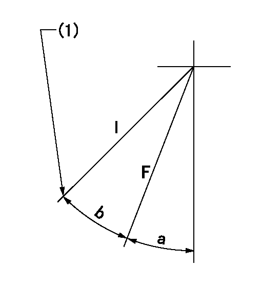
F:Full speed
I:Idle
(1)Stopper bolt setting
----------
----------
a=(4deg)+-5deg b=(18deg)+-5deg
----------
----------
a=(4deg)+-5deg b=(18deg)+-5deg
Stop lever angle
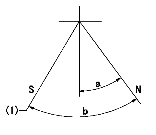
N:Pump normal
S:Stop the pump.
(1)Rack position aa or less, pump speed bb
----------
aa=5.6mm bb=0r/min
----------
a=27deg+-5deg b=53deg+-5deg
----------
aa=5.6mm bb=0r/min
----------
a=27deg+-5deg b=53deg+-5deg
Timing setting

(1)Pump vertical direction
(2)Position of gear's standard threaded hole at No 1 cylinder's beginning of injection
(3)-
(4)-
----------
----------
a=(70deg)
----------
----------
a=(70deg)
Information:
PROBLEM
The spool spring that is internal to the 295-1410 Fuel Injector is failing prematurely on certain FMM and FML engines. Symptoms of this type of failure are consistent with a flutter, skipping, or a fuel knock from the engine at higher speeds. This type of failure is generally a low hour failure.
Note: Use the part hours that are on the fuel injector(s).
AFFECTED PRODUCT
Model Identification Number
DV-3126E FML04334-05512
FMM08554-11449, 11451-11458, 11460-11462, 11464-11466, 11468, 11470-11478, 11481-11488, 11490, 11492-11493, 11495-11496, 11498-11499, 11501-12034
PARTS NEEDED
Qty
Part Number Description
6 10R4763 INJECTOR GP-FUEL
In order to allow equitable parts availability to all participating dealers, please limit your initial parts order to not exceed 27% of dealership population. This is an initial order recommendation only, and the ultimate responsibility for ordering the total number of parts needed to satisfy the program lies with the dealer.
ACTION REQUIRED
Before a parts order can be placed to perform the rework outlined in this service letter, please call:
Todd Bong
Defense and Federal Products
Caterpillar Inc.
309-578-4288
Backup is:
Pat Bowen
Defense and Federal Products
Caterpillar Inc.
309-578-2351
Please have serial number of engines being repaired and number of injectors being needed before making call.
In order to manage the amount of parts on hand, priority of this rework will be managed by Caterpillar.
Take the following actions before or after a failure occurs on one or more injectors in any of the engines listed in this service letter.
- If one or more injectors fail it may be necessary to replace up to 6 injectors at the time of repair.
There will be situations when all 6 injectors do not have to be replaced. Refer to next paragraph to determine which injectors should be replaced.
- If an injector repair has previously been performed after approximately 01Oct07 on any of the listed engines, only the injectors that were not replaced at that time should be replaced. This should further be verified by comparing the injector serial numbers in the engine to a range of 3B115776403B to 3B11676551F9. Disregard the first and last two characters in the serial number (in this case "3B" and "3B" in the first serial number and "3B" and "F9" in the second serial number). The reason for verifying the serial number range is due to a batch change of the internal part that is failing. The change was made after serial number 3B11676551F9.
Only injectors falling within the range of 11577640-11676551 should be replaced.
- If the suspect injector can not be identified by using the automatic cylinder cutout test use the two methods below.
- First, run a manual cylinder cutout test at a high engine speed with some load on the engine. When the injector that has failed is cutout, the sound of the engine should be more normal as opposed to the loud knocking heard when the failed injector is active. The second method is to unplug the wiring harness at the valve cover base that sends current to the injector solenoids as well as the harness connection for the injection actuation pressure sensor. By making these disconnections, the fuel injectors will not fire and