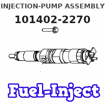
Information injection-pump assembly
BOSCH
9 400 613 867
9400613867
ZEXEL
101402-2270
1014022270
HINO
220204380A
220204380a
Rating:
Service parts 101402-2270 INJECTION-PUMP ASSEMBLY:
1.
_
5.
AUTOM. ADVANCE MECHANIS
6.
COUPLING PLATE
8.
_
9.
_
11.
Nozzle and Holder
23600-1710
12.
Open Pre:MPa(Kqf/cm2)
21.6{220}
15.
NOZZLE SET
Cross reference number
BOSCH
9 400 613 867
9400613867
ZEXEL
101402-2270
1014022270
HINO
220204380A
220204380a
Zexel num
Bosch num
Firm num
Name
101402-2270
9 400 613 867
220204380A HINO
INJECTION-PUMP ASSEMBLY
W04C-T * K 14BC INJECTION PUMP ASSY PE4A,5A, PE
W04C-T * K 14BC INJECTION PUMP ASSY PE4A,5A, PE
Calibration Data:
Adjustment conditions
Test oil
1404 Test oil ISO4113 or {SAEJ967d}
1404 Test oil ISO4113 or {SAEJ967d}
Test oil temperature
degC
40
40
45
Nozzle and nozzle holder
105780-8140
Bosch type code
EF8511/9A
Nozzle
105780-0000
Bosch type code
DN12SD12T
Nozzle holder
105780-2080
Bosch type code
EF8511/9
Opening pressure
MPa
17.2
Opening pressure
kgf/cm2
175
Injection pipe
Outer diameter - inner diameter - length (mm) mm 6-2-600
Outer diameter - inner diameter - length (mm) mm 6-2-600
Overflow valve
134424-0920
Overflow valve opening pressure
kPa
162
147
177
Overflow valve opening pressure
kgf/cm2
1.65
1.5
1.8
Tester oil delivery pressure
kPa
157
157
157
Tester oil delivery pressure
kgf/cm2
1.6
1.6
1.6
Direction of rotation (viewed from drive side)
Right R
Right R
Injection timing adjustment
Direction of rotation (viewed from drive side)
Right R
Right R
Injection order
1-3-4-2
Pre-stroke
mm
3.2
3.17
3.23
Beginning of injection position
Drive side NO.1
Drive side NO.1
Difference between angles 1
Cal 1-3 deg. 90 89.75 90.25
Cal 1-3 deg. 90 89.75 90.25
Difference between angles 2
Cal 1-4 deg. 180 179.75 180.25
Cal 1-4 deg. 180 179.75 180.25
Difference between angles 3
Cyl.1-2 deg. 270 269.75 270.25
Cyl.1-2 deg. 270 269.75 270.25
Injection quantity adjustment
Adjusting point
A
Rack position
8.3
Pump speed
r/min
900
900
900
Average injection quantity
mm3/st.
72.5
70.5
74.5
Max. variation between cylinders
%
0
-3
3
Basic
*
Fixing the rack
*
Injection quantity adjustment_02
Adjusting point
C
Rack position
5.9+-0.5
Pump speed
r/min
410
410
410
Average injection quantity
mm3/st.
10
8.5
11.5
Max. variation between cylinders
%
0
-15
15
Fixing the rack
*
Test data Ex:
Governor adjustment
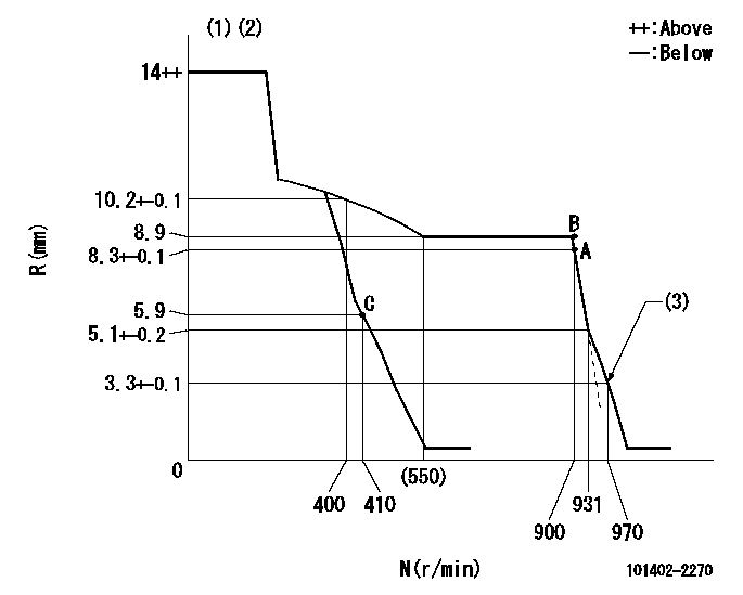
N:Pump speed
R:Rack position (mm)
(1)Target notch: K
(2)Tolerance for racks not indicated: +-0.05mm.
(3)Set idle sub-spring
----------
K=16
----------
----------
K=16
----------
Speed control lever angle
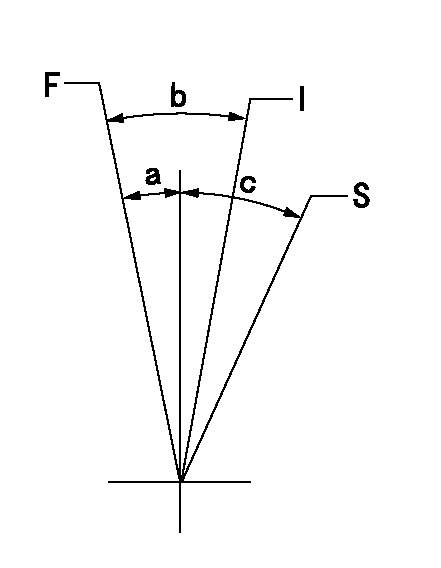
F:Full speed
I:Idle
S:Stop
----------
----------
a=3deg+-5deg b=20deg+-5deg c=32deg+-3deg
----------
----------
a=3deg+-5deg b=20deg+-5deg c=32deg+-3deg
Stop lever angle

N:Pump normal
S:Stop the pump.
(1)Rack position aa or less, pump speed bb
----------
aa=5.4mm bb=0r/min
----------
a=27deg+-5deg b=53deg+-5deg
----------
aa=5.4mm bb=0r/min
----------
a=27deg+-5deg b=53deg+-5deg
Timing setting

(1)Pump vertical direction
(2)Position of gear's standard threaded hole at No 1 cylinder's beginning of injection
(3)-
(4)-
----------
----------
a=(70deg)
----------
----------
a=(70deg)
Information:
Image1.1.1
4) Remove the 90 degree pressure line fitting under the sensor box.
5) Remove the 90 degree pressure line fitting from the DPF center section that is closest to the outlet side.
6) The new pressure line that will fit into the DPF center section will need to be installed into the port in which the thermocouple was fitted. The existing thermocouple will need to be fitted into the port in which the old pressure line was fitted.
Swapping of the ports is only necessary on the outlet side of the center section.
Image1.2.1
Image1.2.2
7) Install the 7W-3556 washer on the 304-8042 straight fitting. Install the straight fitting into the DPF pressure port (towards the outlet side) in which the thermocouple was previously installed, tighten to a torque of 24 +/- 4 Nm (212 +/- 35 lb-in). Screw the 2N-8142 tee fitting onto that straight fitting and tighten to a torque of 24 +/- 4 Nm (212 +/- 35 lb-in).
Image1.3.1
8) Replace the O-ring on the sensor box where the old 90 degree pressure line fitting was located. Install the 4S-4857 tee fitting in the sensor box to a torque of 11 +/- 1 Nm (97 +/- 9 lb-in).
Image1.4.1
9) Where applicable, perform Service Letter REBE3391 at this time.
10) Install sensor box bracket and existing heat shield. Tighten all six bolts to a torque of 12 +/- 3 Nm (106 +/- 27 lb-in).
11) Install sensor box, new pressure lines (tube assemblies), thermocouples onto DPF, and cable straps.
Reference appropriate Disassembly and Assembly manual for proper torque and use of anti-seize.
Image1.5.1
12) Start the engine and use CAT ET to ensure that the status parameter Diesel Particulate Trap #1 Differential Pressure has a value greater than zero. Also, ensure status parameters Diesel Particulate Trap #1 Intake Temperature, and Diesel Particulate Trap #1 Outlet Temperature show reasonable values and increase with the rising exhaust temperatures.
Have questions with 101402-2270?
Group cross 101402-2270 ZEXEL
Hino
101402-2270
9 400 613 867
220204380A
INJECTION-PUMP ASSEMBLY
W04C-T
W04C-T