Information injection-pump assembly
BOSCH
9 400 613 865
9400613865
ZEXEL
101402-2251
1014022251
HINO
220204141A
220204141a
Rating:
Service parts 101402-2251 INJECTION-PUMP ASSEMBLY:
1.
_
5.
AUTOM. ADVANCE MECHANIS
6.
COUPLING PLATE
8.
_
9.
_
11.
Nozzle and Holder
23600-2571A
12.
Open Pre:MPa(Kqf/cm2)
17.7{180}
15.
NOZZLE SET
Cross reference number
BOSCH
9 400 613 865
9400613865
ZEXEL
101402-2251
1014022251
HINO
220204141A
220204141a
Zexel num
Bosch num
Firm num
Name
101402-2251
9 400 613 865
220204141A HINO
INJECTION-PUMP ASSEMBLY
W04D-T K 14BC INJECTION PUMP ASSY PE4A,5A, PE
W04D-T K 14BC INJECTION PUMP ASSY PE4A,5A, PE
Calibration Data:
Adjustment conditions
Test oil
1404 Test oil ISO4113 or {SAEJ967d}
1404 Test oil ISO4113 or {SAEJ967d}
Test oil temperature
degC
40
40
45
Nozzle and nozzle holder
105780-8140
Bosch type code
EF8511/9A
Nozzle
105780-0000
Bosch type code
DN12SD12T
Nozzle holder
105780-2080
Bosch type code
EF8511/9
Opening pressure
MPa
17.2
Opening pressure
kgf/cm2
175
Injection pipe
Outer diameter - inner diameter - length (mm) mm 6-2-600
Outer diameter - inner diameter - length (mm) mm 6-2-600
Overflow valve
131424-5720
Overflow valve opening pressure
kPa
255
221
289
Overflow valve opening pressure
kgf/cm2
2.6
2.25
2.95
Tester oil delivery pressure
kPa
157
157
157
Tester oil delivery pressure
kgf/cm2
1.6
1.6
1.6
Direction of rotation (viewed from drive side)
Right R
Right R
Injection timing adjustment
Direction of rotation (viewed from drive side)
Right R
Right R
Injection order
1-3-4-2
Pre-stroke
mm
4.4
4.35
4.45
Beginning of injection position
Drive side NO.1
Drive side NO.1
Difference between angles 1
Cal 1-3 deg. 90 89.5 90.5
Cal 1-3 deg. 90 89.5 90.5
Difference between angles 2
Cal 1-4 deg. 180 179.5 180.5
Cal 1-4 deg. 180 179.5 180.5
Difference between angles 3
Cyl.1-2 deg. 270 269.5 270.5
Cyl.1-2 deg. 270 269.5 270.5
Injection quantity adjustment
Adjusting point
A
Rack position
9.9
Pump speed
r/min
1150
1150
1150
Average injection quantity
mm3/st.
80
78
82
Max. variation between cylinders
%
0
-3
3
Basic
*
Fixing the lever
*
Boost pressure
kPa
46.7
46.7
Boost pressure
mmHg
350
350
Injection quantity adjustment_02
Adjusting point
-
Rack position
7.1+-0.5
Pump speed
r/min
475
475
475
Average injection quantity
mm3/st.
9
7.5
10.5
Max. variation between cylinders
%
0
-15
15
Fixing the rack
*
Boost pressure
kPa
0
0
0
Boost pressure
mmHg
0
0
0
Remarks
Adjust only variation between cylinders; adjust governor according to governor specifications.
Adjust only variation between cylinders; adjust governor according to governor specifications.
Injection quantity adjustment_03
Adjusting point
E
Rack position
-
Pump speed
r/min
100
100
100
Average injection quantity
mm3/st.
100
100
110
Fixing the lever
*
Boost pressure
kPa
0
0
0
Boost pressure
mmHg
0
0
0
Rack limit
*
Boost compensator adjustment
Pump speed
r/min
600
600
600
Rack position
R1-0.5
Boost pressure
kPa
21.3
18.6
24
Boost pressure
mmHg
160
140
180
Boost compensator adjustment_02
Pump speed
r/min
600
600
600
Rack position
R1(9.9)
Boost pressure
kPa
33.3
26.6
40
Boost pressure
mmHg
250
200
300
Test data Ex:
Governor adjustment
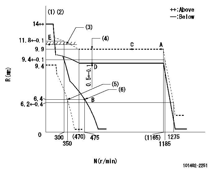
N:Pump speed
R:Rack position (mm)
(1)Target notch: K
(2)Tolerance for racks not indicated: +-0.05mm.
(3)RACK LIMIT
(4)Boost compensator stroke (at N = N1)
(5)Set idle sub-spring
(6)Main spring setting
----------
K=18 N1=600r/min
----------
----------
K=18 N1=600r/min
----------
Speed control lever angle
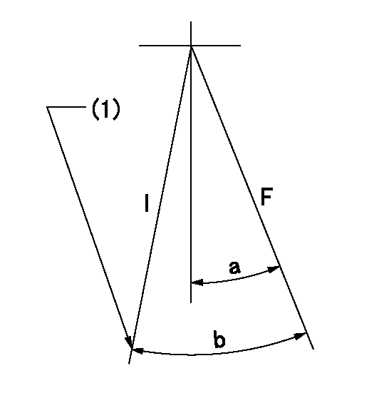
F:Full speed
I:Idle
(1)Stopper bolt setting
----------
----------
a=(28deg)+-5deg b=(32deg)+-5deg
----------
----------
a=(28deg)+-5deg b=(32deg)+-5deg
Stop lever angle

N:Pump normal
S:Stop the pump.
(1)Pump speed aa and rack position bb (to be sealed at delivery)
----------
aa=0r/min bb=1-0.2mm
----------
a=21deg+-5deg b=(55deg)
----------
aa=0r/min bb=1-0.2mm
----------
a=21deg+-5deg b=(55deg)
Timing setting

(1)Pump vertical direction
(2)Position of gear's standard threaded hole at No 1 cylinder's beginning of injection
(3)-
(4)-
----------
----------
a=(70deg)
----------
----------
a=(70deg)
Information:
PARTS NEEDED
Qty
Part Number Description
*******Group 1*******
6 2530618 INJECTOR GP-FUEL
1 3085693 SOFTWARE GP-ELEK
In Order to allow equitable parts availability to all participating dealers, please limit your initial parts order to not exceed 40% of dealership population. This is an initial order recommendation only, and the ultimate responsibility for ordering the total number of parts needed to satisfy the program lies with the dealer.
*******Group 2*******
1 3085693 SOFTWARE GP-ELEK
In Order to allow equitable parts availability to all participating dealers, please limit your initial parts order to not exceed 40% of dealership population. This is an initial order recommendation only, and the ultimate responsibility for ordering the total number of parts needed to satisfy the program lies with the dealer.
ACTION REQUIRED
Group 1 Engines:
Remove the existing 291-5911 injectors and replace with a new set of 253-0618 injectors. Once this is complete, flash the Engine ECM with the 308-5693 software file.
Group 2 Engines:
Flash the Engine Ecm with the 308-5693 software file.
OWNER NOTIFICATION
U.S. and Canadian owners will receive the attached Owner Notification.
SERVICE CLAIM ALLOWANCES
Caterpillar Dealer Suggested Customer Suggested
Parts % Labor Hrs% Parts % Labor Hrs% Parts % Labor Hrs%
*******Group 1*******
100% 100% 0% 0% 0% 0%
This is a 3.0-hour job for Group 1
Caterpillar Dealer Suggested Customer Suggested
Parts % Labor Hrs% Parts % Labor Hrs% Parts % Labor Hrs%
*******Group 2*******
100% 100% 0% 0% 0% 0%
This is a 1.0-hour job for Group 2
PARTS DISPOSITION
Handle the parts in accordance with your Warranty Bulletin on warranty parts handling.
MAKE EVERY EFFORT TO COMPLETE THIS PROGRAM AS SOON AS POSSIBLE.
COPY OF OWNER NOTIFICATION FOR U.S. AND CANADIAN OWNERS
XYZ Corporation
3240 Arrow Drive
Anywhere, YZ 99999
PRIORITY - PRODUCT IMPROVEMENT PROGRAM FOR REPLACING THE ENGINE ELECTRONIC CONTROL MODULE (ECM) SOFTWARE AND POSSIBLY THE INJECTORS ON CERTAIN C18 INDUSTRIAL ENGINES
MODELS INVOLVED - C18 Industrial Engines
Dear Caterpillar Product Owner:
The Engine software and possibly the injectors need to be replaced on the C18 Industrial Engines listed below. The existing injectors do not work properly with the current software. You will not be charged for the service performed.
Contact your local Caterpillar dealer immediately to schedule this service. The dealer will advise you of the time required to complete this service.
Please refer the dealer to their Service Letter dated 28Feb2008 when scheduling this service.
We regret the inconvenience this may cause you, but urge you to have this service performed as soon as possible to prevent unscheduled downtime.
Caterpillar Inc.
Identification #(s)
Attached to 28Feb2008 Service Letter
Have questions with 101402-2251?
Group cross 101402-2251 ZEXEL
Hino
101402-2251
9 400 613 865
220204141A
INJECTION-PUMP ASSEMBLY
W04D-T
W04D-T