Information injection-pump assembly
BOSCH
F 019 Z10 570
f019z10570
ZEXEL
101402-2221
1014022221
HINO
220203841A
220203841a
Rating:
Service parts 101402-2221 INJECTION-PUMP ASSEMBLY:
1.
_
5.
AUTOM. ADVANCE MECHANIS
6.
COUPLING PLATE
8.
_
9.
_
11.
Nozzle and Holder
12.
Open Pre:MPa(Kqf/cm2)
21.6(220)
15.
NOZZLE SET
Cross reference number
BOSCH
F 019 Z10 570
f019z10570
ZEXEL
101402-2221
1014022221
HINO
220203841A
220203841a
Zexel num
Bosch num
Firm num
Name
Calibration Data:
Adjustment conditions
Test oil
1404 Test oil ISO4113 or {SAEJ967d}
1404 Test oil ISO4113 or {SAEJ967d}
Test oil temperature
degC
40
40
45
Nozzle and nozzle holder
105780-8140
Bosch type code
EF8511/9A
Nozzle
105780-0000
Bosch type code
DN12SD12T
Nozzle holder
105780-2080
Bosch type code
EF8511/9
Opening pressure
MPa
17.2
Opening pressure
kgf/cm2
175
Injection pipe
Outer diameter - inner diameter - length (mm) mm 6-2-600
Outer diameter - inner diameter - length (mm) mm 6-2-600
Overflow valve
131424-5720
Overflow valve opening pressure
kPa
255
221
289
Overflow valve opening pressure
kgf/cm2
2.6
2.25
2.95
Tester oil delivery pressure
kPa
157
157
157
Tester oil delivery pressure
kgf/cm2
1.6
1.6
1.6
Direction of rotation (viewed from drive side)
Right R
Right R
Injection timing adjustment
Direction of rotation (viewed from drive side)
Right R
Right R
Injection order
1-3-4-2
Pre-stroke
mm
4.4
4.35
4.45
Beginning of injection position
Drive side NO.1
Drive side NO.1
Difference between angles 1
Cal 1-3 deg. 90 89.5 90.5
Cal 1-3 deg. 90 89.5 90.5
Difference between angles 2
Cal 1-4 deg. 180 179.5 180.5
Cal 1-4 deg. 180 179.5 180.5
Difference between angles 3
Cyl.1-2 deg. 270 269.5 270.5
Cyl.1-2 deg. 270 269.5 270.5
Injection quantity adjustment
Adjusting point
A
Rack position
12.2
Pump speed
r/min
1500
1500
1500
Average injection quantity
mm3/st.
143
141
145
Max. variation between cylinders
%
0
-3
3
Basic
*
Fixing the lever
*
Boost pressure
kPa
80
80
Boost pressure
mmHg
600
600
Injection quantity adjustment_02
Adjusting point
B
Rack position
7.1+-0.5
Pump speed
r/min
400
400
400
Average injection quantity
mm3/st.
16.5
15
18
Max. variation between cylinders
%
0
-15
15
Fixing the rack
*
Boost pressure
kPa
0
0
0
Boost pressure
mmHg
0
0
0
Boost compensator adjustment
Pump speed
r/min
700
700
700
Rack position
R1-2.8
Boost pressure
kPa
12
9.3
14.7
Boost pressure
mmHg
90
70
110
Boost compensator adjustment_02
Pump speed
r/min
700
700
700
Rack position
R1(12.2)
Boost pressure
kPa
66.7
66.7
66.7
Boost pressure
mmHg
500
500
500
Test data Ex:
Governor adjustment
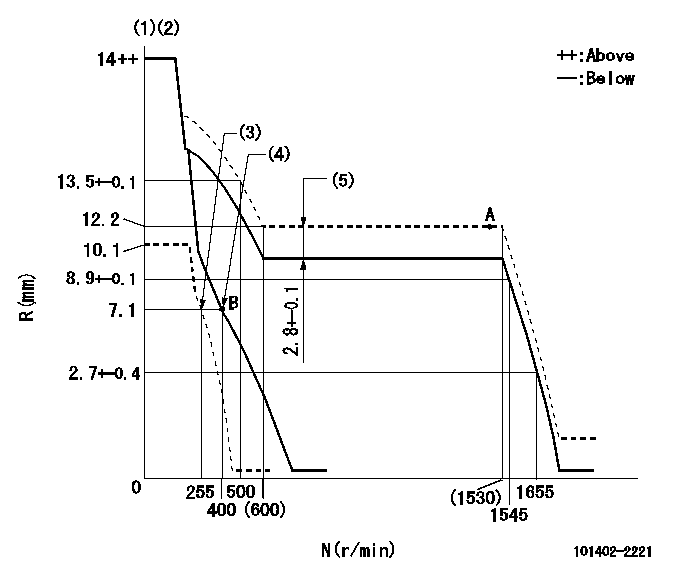
N:Pump speed
R:Rack position (mm)
(1)Target notch: K
(2)Tolerance for racks not indicated: +-0.05mm.
(3)Set idle sub-spring
(4)Main spring setting
(5)Boost compensator stroke
----------
K=8
----------
----------
K=8
----------
Speed control lever angle

F:Full speed
I:Idle
(1)Stopper bolt setting
----------
----------
a=24deg+-5deg b=26deg+-5deg
----------
----------
a=24deg+-5deg b=26deg+-5deg
Stop lever angle
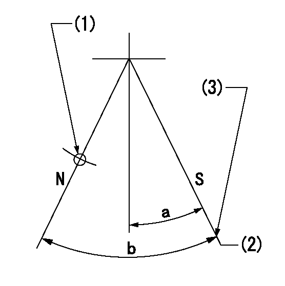
N:Pump normal
S:Stop the pump.
(1)Use the hole at R = aa
(2)Speed = bb, rack position = cc (sealed at delivery)
(3)Stopper bolt setting
----------
aa=25mm bb=0r/min cc=1-0.5mm
----------
a=21deg+-5deg b=(55deg)
----------
aa=25mm bb=0r/min cc=1-0.5mm
----------
a=21deg+-5deg b=(55deg)
Timing setting

(1)Pump vertical direction
(2)Position of gear's standard threaded hole at No 1 cylinder's beginning of injection
(3)-
(4)-
----------
----------
a=(70deg)
----------
----------
a=(70deg)
Information:
U-457
TT-31
Before/After
PRODUCT SUPPORT PROGRAM FOR REWORKING INTERNAL INJECTOR HARNESS TRAYS ON 2007 C9 ENGINES
1408 PS42515
This Program must be administered either before or after failure.In either case the decision whether to apply the Program is made by the dealer. When reporting the repair, use "PS42515" as the Part Numberand "7755" as the Group Number. If administered before failure, use "56" as the Warranty Claim Description Code and "T" as the SIMS Description code.If administered after failure, use "96" as the Warranty Claim Description Code, and "Z" as the SIMS Description Code.
The information supplied in this service letter may not be valid after the termination date of this program.Do not perform the work outlined in this Service Letter after the termination date without first contacting your Caterpillar product analyst.
TERMINATION DATE
30Sep2009
PROBLEM
The existing internal injector harness tray can fracture on certain 2007 C9 engines. If the existing internal injector harness tray fails it can cause metal debris to enter the system.
AFFECTED PRODUCT
Model Identification Number
C9 C9S00500-00507, 522-523, 527, 531, 534-576, 578-633, 635-654, 656-657
PARTS NEEDED
Qty
Part Number Description
5 9L9132 WASHER-HARD
ACTION REQUIRED
Follow Special Instructions REHS3812 for rework procedure.
SERVICE CLAIM ALLOWANCES
Product smu/age whichever comes first Caterpillar Dealer Suggested Customer Suggested
Parts % Labor Hrs% Parts % Labor Hrs% Parts % Labor Hrs%
0-250000 miles,
0-24 mo 100.0% 100.0% 0.0% 0.0% 0.0% 0.0%
This is a 2.0-hour job
Dealer to perform most economical repair
Description____________SMCS CODE________Hours
Engine Wash____________1000-074_________0.3
R&I Valve Cover________1107-010_________0.5
Valve Cover Wash_______1107-074_________0.3
Troubleshoot Harness___1408-035_________0.6
Minor Road Test________1000-530_________0.3
Exception may be be considered and claimed depending on chassis type.
PARTS DISPOSITION
Handle the parts in accordance with your Warranty Bulletin on warranty parts handling.