Information injection-pump assembly
ZEXEL
101402-2220
1014022220
HINO
220203840A
220203840a
Rating:
Service parts 101402-2220 INJECTION-PUMP ASSEMBLY:
1.
_
5.
AUTOM. ADVANCE MECHANIS
6.
COUPLING PLATE
8.
_
9.
_
11.
Nozzle and Holder
23600-1780
12.
Open Pre:MPa(Kqf/cm2)
21.6{220}
15.
NOZZLE SET
Cross reference number
ZEXEL
101402-2220
1014022220
HINO
220203840A
220203840a
Zexel num
Bosch num
Firm num
Name
Calibration Data:
Adjustment conditions
Test oil
1404 Test oil ISO4113 or {SAEJ967d}
1404 Test oil ISO4113 or {SAEJ967d}
Test oil temperature
degC
40
40
45
Nozzle and nozzle holder
105780-8140
Bosch type code
EF8511/9A
Nozzle
105780-0000
Bosch type code
DN12SD12T
Nozzle holder
105780-2080
Bosch type code
EF8511/9
Opening pressure
MPa
17.2
Opening pressure
kgf/cm2
175
Injection pipe
Outer diameter - inner diameter - length (mm) mm 6-2-600
Outer diameter - inner diameter - length (mm) mm 6-2-600
Overflow valve
131424-6420
Overflow valve opening pressure
kPa
255
221
289
Overflow valve opening pressure
kgf/cm2
2.6
2.25
2.95
Tester oil delivery pressure
kPa
157
157
157
Tester oil delivery pressure
kgf/cm2
1.6
1.6
1.6
Direction of rotation (viewed from drive side)
Right R
Right R
Injection timing adjustment
Direction of rotation (viewed from drive side)
Right R
Right R
Injection order
1-3-4-2
Pre-stroke
mm
4.4
4.35
4.45
Beginning of injection position
Drive side NO.1
Drive side NO.1
Difference between angles 1
Cal 1-3 deg. 90 89.5 90.5
Cal 1-3 deg. 90 89.5 90.5
Difference between angles 2
Cal 1-4 deg. 180 179.5 180.5
Cal 1-4 deg. 180 179.5 180.5
Difference between angles 3
Cyl.1-2 deg. 270 269.5 270.5
Cyl.1-2 deg. 270 269.5 270.5
Injection quantity adjustment
Adjusting point
A
Rack position
11.9
Pump speed
r/min
1500
1500
1500
Average injection quantity
mm3/st.
130.4
128.4
132.4
Max. variation between cylinders
%
0
-3
3
Basic
*
Fixing the lever
*
Boost pressure
kPa
80
80
Boost pressure
mmHg
600
600
Injection quantity adjustment_02
Adjusting point
B
Rack position
7.6+-0.5
Pump speed
r/min
400
400
400
Average injection quantity
mm3/st.
16.5
15
18
Max. variation between cylinders
%
0
-15
15
Fixing the rack
*
Boost pressure
kPa
0
0
0
Boost pressure
mmHg
0
0
0
Boost compensator adjustment
Pump speed
r/min
600
600
600
Rack position
R1-2.8
Boost pressure
kPa
12
9.3
14.7
Boost pressure
mmHg
90
70
110
Boost compensator adjustment_02
Pump speed
r/min
600
600
600
Rack position
R1(11.9)
Boost pressure
kPa
66.7
66.7
66.7
Boost pressure
mmHg
500
500
500
Test data Ex:
Governor adjustment
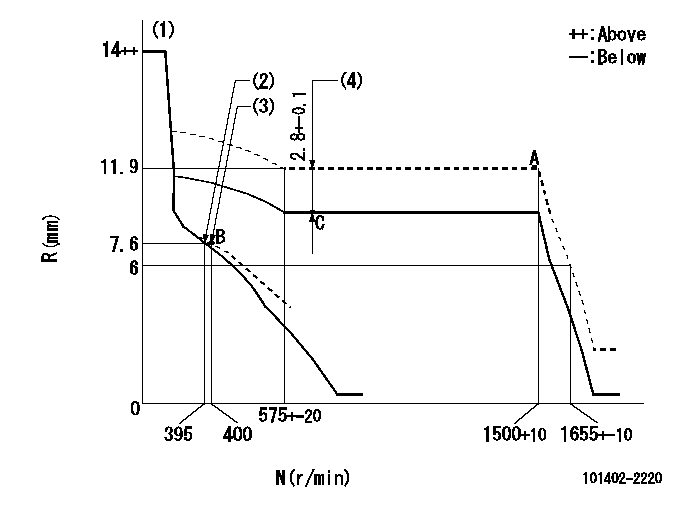
N:Pump speed
R:Rack position (mm)
(1)Target notch: K
(2)Main spring setting
(3)Set idle sub-spring
(4)Boost compensator stroke (at N = N1)
----------
K=14 N1=600r/min
----------
----------
K=14 N1=600r/min
----------
Speed control lever angle
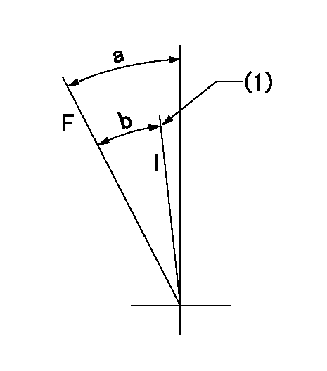
F:Full speed
I:Idle
(1)Stopper bolt setting
----------
----------
a=(31deg)+-5deg b=(26deg)+-5deg
----------
----------
a=(31deg)+-5deg b=(26deg)+-5deg
Stop lever angle

N:Pump normal
S:Stop the pump.
(1)Speed = aa, rack position = bb (sealed at shipping)
----------
aa=0r/min bb=1-0.2mm
----------
a=21deg+-5deg b=(55deg)
----------
aa=0r/min bb=1-0.2mm
----------
a=21deg+-5deg b=(55deg)
Timing setting

(1)Pump vertical direction
(2)Position of gear's standard threaded hole at No 1 cylinder's beginning of injection
(3)-
(4)-
----------
----------
a=(70deg)
----------
----------
a=(70deg)
Information:
AFFECTED PRODUCT
Model Identification Number
C9 MTB00101-00106, 109-190, 197-199, 1000-1001, 1003-1005, 1007-1221, 1227-1387, 1396-1429, 1431-1464, 1467-1550, 1553-2020
PARTS NEEDED
Qty
Part Number Description
6 1093207 SEAL-O-RING
12 1482903 SEAL-O-RING
6 1495240 RING-BACKUP
6 2271200 SLEEVE-INJECTOR
6 2930730 RING-BACKUP
6 3107255 SEAL-O-RING
6 3107257 SEAL-O-RING
ACTION REQUIRED
Follow Special Instruction REHS3798 for proper installation of injector sleeve o-rings.
Injector o-rings need to be replaced when the injector is removed to perform sleeve o-ring replacement. Reference SEBD6792 for correct orientation of injector o-rings.
OWNER NOTIFICATION
U.S. and Canadian owners will receive the attached Owner Notification.
SERVICE CLAIM ALLOWANCES
Caterpillar Dealer Suggested Customer Suggested
Parts % Labor Hrs% Parts % Labor Hrs% Parts % Labor Hrs%
100% 100% 0% 0% 0% 0%
This is a 9.6-hour job
*Dealer to perform most economical repair*
Description_____________SMCS Code_________Hours
Wash____________________1290-074__________0.3
R&I Injectors___________1290-010-S________4.2
Remove Sleeve___________1713-011__________1.3
Clean Sleeve Bore_______1713-70-BO________0.8
Install sleeve seals____1713-012-SA_______0.8
Install Sleeve set______1713-012-S________1.7
Test After______________1290-030__________0.5
*Exception may be considered and claimed depending on chassis type*
PARTS DISPOSITION
Handle the parts in accordance with your Warranty Bulletin on warranty parts handling.
MAKE EVERY EFFORT TO COMPLETE THIS PROGRAM AS SOON AS POSSIBLE.
COPY OF OWNER NOTIFICATION FOR U.S. AND CANADIAN OWNERS
XYZ Corporation
3240 Arrow Drive
Anywhere, YZ 99999
PRIORITY - PRODUCT IMPROVEMENT PROGRAM FOR REPLACING INJECTOR SLEEVE O-RINGS ON CERTAIN C9 MTB ON-HIGHWAY TRUCK ENGINES
MODELS INVOLVED - C9 Mass Transit Bus Engines
Dear Caterpillar Product Owner:
The injector sleeve o-rings need to be replaced on certain C9 MTB On-Highway truck engines. The existing o-rings can cause fuel to enter the coolant system if failure occurs. You will not be charged for the service performed.
Contact your local Caterpillar dealer immediately to schedule this service. The dealer will advise you of the time required to complete this service.
Please refer the dealer to their Service Letter dated 20Sep2007 when scheduling this service.
We regret the inconvenience this may cause you, but urge you to have this service performed as soon as possible to prevent unscheduled downtime.
Caterpillar Inc.
Identification #(s)
Attached to 20Sep2007 Service Letter