Information injection-pump assembly
BOSCH
9 400 613 857
9400613857
ZEXEL
101402-2140
1014022140
HINO
220203410A
220203410a

Rating:
Service parts 101402-2140 INJECTION-PUMP ASSEMBLY:
1.
_
5.
AUTOM. ADVANCE MECHANIS
6.
COUPLING PLATE
8.
_
9.
_
11.
Nozzle and Holder
23600-1710
12.
Open Pre:MPa(Kqf/cm2)
21.6{220}
15.
NOZZLE SET
Cross reference number
BOSCH
9 400 613 857
9400613857
ZEXEL
101402-2140
1014022140
HINO
220203410A
220203410a
Zexel num
Bosch num
Firm num
Name
101402-2140
9 400 613 857
220203410A HINO
INJECTION-PUMP ASSEMBLY
W04C-T K 14BC INJECTION PUMP ASSY PE4A,5A, PE
W04C-T K 14BC INJECTION PUMP ASSY PE4A,5A, PE
Calibration Data:
Adjustment conditions
Test oil
1404 Test oil ISO4113 or {SAEJ967d}
1404 Test oil ISO4113 or {SAEJ967d}
Test oil temperature
degC
40
40
45
Nozzle and nozzle holder
105780-8140
Bosch type code
EF8511/9A
Nozzle
105780-0000
Bosch type code
DN12SD12T
Nozzle holder
105780-2080
Bosch type code
EF8511/9
Opening pressure
MPa
17.2
Opening pressure
kgf/cm2
175
Injection pipe
Outer diameter - inner diameter - length (mm) mm 6-2-600
Outer diameter - inner diameter - length (mm) mm 6-2-600
Overflow valve
134424-0920
Overflow valve opening pressure
kPa
162
147
177
Overflow valve opening pressure
kgf/cm2
1.65
1.5
1.8
Tester oil delivery pressure
kPa
157
157
157
Tester oil delivery pressure
kgf/cm2
1.6
1.6
1.6
Direction of rotation (viewed from drive side)
Right R
Right R
Injection timing adjustment
Direction of rotation (viewed from drive side)
Right R
Right R
Injection order
1-3-4-2
Pre-stroke
mm
3.2
3.17
3.23
Beginning of injection position
Drive side NO.1
Drive side NO.1
Difference between angles 1
Cal 1-3 deg. 90 89.75 90.25
Cal 1-3 deg. 90 89.75 90.25
Difference between angles 2
Cal 1-4 deg. 180 179.75 180.25
Cal 1-4 deg. 180 179.75 180.25
Difference between angles 3
Cyl.1-2 deg. 270 269.75 270.25
Cyl.1-2 deg. 270 269.75 270.25
Injection quantity adjustment
Adjusting point
A
Rack position
10.4
Pump speed
r/min
900
900
900
Average injection quantity
mm3/st.
74
72
76
Max. variation between cylinders
%
0
-3
3
Basic
*
Fixing the lever
*
Injection quantity adjustment_02
Adjusting point
C
Rack position
7.7+-0.5
Pump speed
r/min
600
600
600
Average injection quantity
mm3/st.
22.8
21.3
24.3
Max. variation between cylinders
%
0
-15
15
Fixing the rack
*
Test data Ex:
Governor adjustment
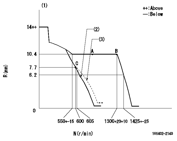
N:Pump speed
R:Rack position (mm)
(1)Target notch: K
(2)Main spring setting
(3)Set idle sub-spring
----------
K=14
----------
----------
K=14
----------
Speed control lever angle
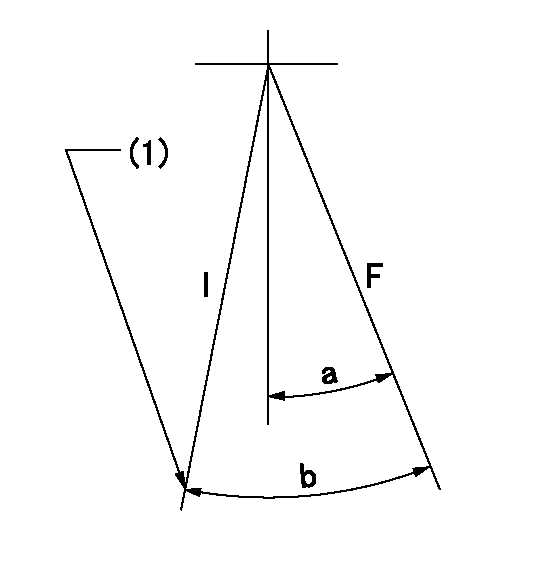
F:Full speed
I:Idle
(1)Stopper bolt setting
----------
----------
a=16deg+-5deg b=20deg+-5deg
----------
----------
a=16deg+-5deg b=20deg+-5deg
Stop lever angle
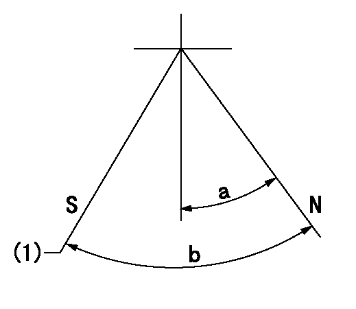
N:Pump normal
S:Stop the pump.
(1)At shipping
----------
----------
a=27deg+-5deg b=53deg+-5deg
----------
----------
a=27deg+-5deg b=53deg+-5deg
Timing setting

(1)Pump vertical direction
(2)Position of gear's standard threaded hole at No 1 cylinder's beginning of injection
(3)-
(4)-
----------
----------
a=(70deg)
----------
----------
a=(70deg)
Information:
AUGUST 2010
INFORMATION RELEASE MEMO
Reman
PELJ1207 ?2010 Caterpillar CAT REMAN ANNOUNCES AN APPEARANCE CHANGE TO CERTAIN 3406 AND 3500 ELECTRONIC UNIT INJECTORS
Announcement
Cat Reman announces an appearance change to certain 3406 and 3500 electronic unit injectors. Effective immediately, certain remanufactured electronic unit injectors for 3406 and 3500 engines will be produced with stators, which have been ground slightly around the outside to remove potentially obsolete identification information. In many cases, these remanufactured injectors were previously produced with a metal sleeve around the outside of the stator to cover any potentially obsolete identifying information. Dealers will see both sleeved and ground stators for some period of time. This change will not impact quality, performance, form, fit, or function.
Effective immediately, Figure 1 and Figure 2 willboth represent acceptable appearance for the affected electronic unit injector part numbers. Table 1 lists all affected part numbers.
Core Acceptance
Core Acceptance Criteria for Cat Reman parts is simple, visual, and requires no special tools. Consult the Unit Injectors Electronic Core Acceptance Criteria (SELD0226) for complete details.
Warranty
Please consult the appropriate Caterpillar parts warranty statement for your area.
Core Management
Please refer to the Cat Core Management Information System (CMIS 2) Parts Information application describing all Cat Reman part/CAF and related information. Also refer to other CMIS 2 inquiry applications such as Customer Profiles, Inspection Reason Codes, Inspection Line Inquiry, Add Charge Information, Entitlement Activity, Entitlement Inquiry, CCR Inquiry, CCR Entry, Shipment Processing; Process Packaging Grief; and Reporting to properly manage core returns and monitor inspection performance. This information will be available to all dealers worldwide after your CMIS 2 conversion date. In the meantime, please continue to use the current CMIS Entitlement Parts Inquiry Screen describing the list of parts in a Core Acceptability Family (CAF) and related part number detail.
For the latest updates of Reman Policies and Core Management (SELD0122), Core Management Systems & Operations Procedures (SELD0040), and Shipping Instructions (SELD0039), go to the Reman Dealer website https://catreman.cat.com. If you have any questions regarding core return processing, feel free to call Corinth toll free at (800) 537-2928. Outside the US please refer to the Core section of the Reman website for appropriate contact information for your region.
For assistance with technical questions, call the Peoria Reman Technical Help Line also toll free at (888) 88-REMAN (outside the US call non-toll free +1-309-494-4342), or use our E-mail address--Reman_Help.
Have questions with 101402-2140?
Group cross 101402-2140 ZEXEL
Hino
101402-2140
9 400 613 857
220203410A
INJECTION-PUMP ASSEMBLY
W04C-T
W04C-T