Information injection-pump assembly
BOSCH
9 400 613 842
9400613842
ZEXEL
101402-0981
1014020981
ISUZU
8943251111
8943251111
Rating:
Service parts 101402-0981 INJECTION-PUMP ASSEMBLY:
1.
_

5.
AUTOM. ADVANCE MECHANIS
6.
COUPLING PLATE
8.
_
9.
_
11.
Nozzle and Holder
1-15300-105-2
12.
Open Pre:MPa(Kqf/cm2)
18.1{185}

15.
NOZZLE SET
Cross reference number
BOSCH
9 400 613 842
9400613842
ZEXEL
101402-0981
1014020981
ISUZU
8943251111
8943251111
Zexel num
Bosch num
Firm num
Name
9 400 613 842
8943251111 ISUZU
INJECTION-PUMP ASSEMBLY
4BD1 K 14BC INJECTION PUMP ASSY PE4A,5A, PE
4BD1 K 14BC INJECTION PUMP ASSY PE4A,5A, PE
Calibration Data:
Adjustment conditions
Test oil
1404 Test oil ISO4113 or {SAEJ967d}
1404 Test oil ISO4113 or {SAEJ967d}
Test oil temperature
degC
40
40
45
Nozzle and nozzle holder
105780-8140
Bosch type code
EF8511/9A
Nozzle
105780-0000
Bosch type code
DN12SD12T
Nozzle holder
105780-2080
Bosch type code
EF8511/9
Opening pressure
MPa
17.2
Opening pressure
kgf/cm2
175
Injection pipe
Outer diameter - inner diameter - length (mm) mm 6-2-600
Outer diameter - inner diameter - length (mm) mm 6-2-600
Tester oil delivery pressure
kPa
157
157
157
Tester oil delivery pressure
kgf/cm2
1.6
1.6
1.6
Direction of rotation (viewed from drive side)
Right R
Right R
Injection timing adjustment
Direction of rotation (viewed from drive side)
Right R
Right R
Injection order
1-3-4-2
Pre-stroke
mm
3.4
3.35
3.45
Beginning of injection position
Drive side NO.1
Drive side NO.1
Difference between angles 1
Cal 1-3 deg. 90 89.5 90.5
Cal 1-3 deg. 90 89.5 90.5
Difference between angles 2
Cal 1-4 deg. 180 179.5 180.5
Cal 1-4 deg. 180 179.5 180.5
Difference between angles 3
Cyl.1-2 deg. 270 269.5 270.5
Cyl.1-2 deg. 270 269.5 270.5
Injection quantity adjustment
Adjusting point
A
Rack position
9.7
Pump speed
r/min
800
800
800
Average injection quantity
mm3/st.
71.8
70.3
73.3
Max. variation between cylinders
%
0
-2
2
Basic
*
Fixing the lever
*
Injection quantity adjustment_02
Adjusting point
C
Rack position
6.6+-0.5
Pump speed
r/min
350
350
350
Average injection quantity
mm3/st.
8
6.6
9.4
Max. variation between cylinders
%
0
-14
14
Fixing the rack
*
Test data Ex:
Governor adjustment
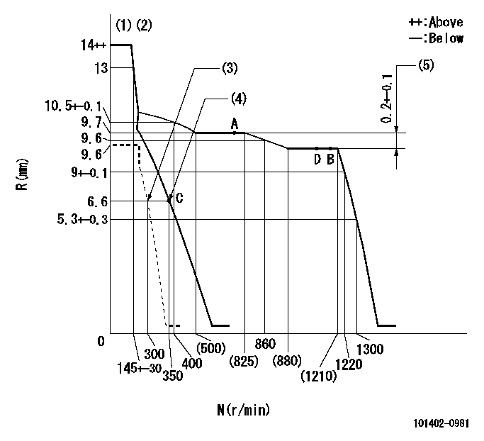
N:Pump speed
R:Rack position (mm)
(1)Target notch: K
(2)Tolerance for racks not indicated: +-0.05mm.
(3)Set idle sub-spring
(4)Main spring setting
(5)Rack difference between N = N1 and N = N2
----------
K=15 N1=1150r/min N2=800r/min
----------
----------
K=15 N1=1150r/min N2=800r/min
----------
Speed control lever angle

F:Full speed
I:Idle
(1)Stopper bolt setting
----------
----------
a=16eg+-5deg b=31deg+-5deg
----------
----------
a=16eg+-5deg b=31deg+-5deg
Stop lever angle

N:Pump normal
S:Stop the pump.
----------
----------
a=19deg+-5deg b=53deg+-5deg
----------
----------
a=19deg+-5deg b=53deg+-5deg
Timing setting

(1)Pump vertical direction
(2)Position of gear mark 'CC' at No 1 cylinder's beginning of injection
(3)B.T.D.C.: aa
(4)-
----------
aa=18deg
----------
a=(90deg)
----------
aa=18deg
----------
a=(90deg)
Information:
Above Normal Heating
Low Coolant Level ... If the coolant level is too low, not enough coolant will go through the engine and radiator. This lack of coolant will not take enough heat from the engine and there will not be enough coolant flow through the radiator to release the heat into the cooling air. Low coolant level is caused by leaks or wrong filling of the radiator. With the engine cool, be sure that coolant can be seen at the low end of the fill neck or at the sight glass on the radiator top tank.Defective Temperature Gauge ... A temperature gauge which does not work correctly will not show the correct temperature. If the temperature gauge shows that the coolant temperature is to hot but other conditions are normal, install a thermometer you know is correct and/or check the cooling system.Dirty Radiator ... Check the radiator core for debris which prevents free air flow. Check the radiator for debris, dirt, or deposits on the inside of the radiator core which prevents free flow of coolant through the radiator.Loose Belts ... Loose fan or water pump belts will cause a reduction in air or water flow. Tighten belts until a 25 lb. (11,3 kg) force at the half way point between the pulleys, moves the belts .875 .125 in. (22,0 3,0 mm).Defective Hoses ... Leaks in hoses can normally be seen. Hoses that have no visual leaks can collapse during operation and cause restriction in the flow of coolant. Hoses become soft and/or get cracks after a period of time. Change hoses after a year of use. The inside can become loose and the loose particles can cause a restriction in the flow of coolant.Shunt Line Restriction ... A restriction of the shunt line from the radiator top tank to the engine front cover, or a shunt line not installed correctly, will cause a reduction in water pump efficiency. The result will be low coolant flow and over-heating.Shutters Not Opening Correctly ... Check the opening temperature of the shutters. The shutters must be open at 200°F (93°C).Defective Thermostats ... A thermostat that does not open or only opens part of the way can cause above normal heating. To test the thermostats, see the topic WATER TEMPERATURE THERMOSTAT.Defective Water Pump* ... A water pump with a loose pulley or impeller does not pump enough coolant for correct engine cooling. A loose pulley or impeller can be found by removing the drive belt for the water pump and by pushing the pulley back and pulling it forward.Air in Cooling System ... Air can get into the cooling system in different ways. The most common causes are not filling the cooling system correctly, and combustion gas leaking into the system. Combustion gas can get into the system through inside cracks or bad cylinder head gaskets. Air in the cooling system causes a reduction in coolant flow and bubbles in the coolant. Air bubbles hold coolant away from engine parts,
Low Coolant Level ... If the coolant level is too low, not enough coolant will go through the engine and radiator. This lack of coolant will not take enough heat from the engine and there will not be enough coolant flow through the radiator to release the heat into the cooling air. Low coolant level is caused by leaks or wrong filling of the radiator. With the engine cool, be sure that coolant can be seen at the low end of the fill neck or at the sight glass on the radiator top tank.Defective Temperature Gauge ... A temperature gauge which does not work correctly will not show the correct temperature. If the temperature gauge shows that the coolant temperature is to hot but other conditions are normal, install a thermometer you know is correct and/or check the cooling system.Dirty Radiator ... Check the radiator core for debris which prevents free air flow. Check the radiator for debris, dirt, or deposits on the inside of the radiator core which prevents free flow of coolant through the radiator.Loose Belts ... Loose fan or water pump belts will cause a reduction in air or water flow. Tighten belts until a 25 lb. (11,3 kg) force at the half way point between the pulleys, moves the belts .875 .125 in. (22,0 3,0 mm).Defective Hoses ... Leaks in hoses can normally be seen. Hoses that have no visual leaks can collapse during operation and cause restriction in the flow of coolant. Hoses become soft and/or get cracks after a period of time. Change hoses after a year of use. The inside can become loose and the loose particles can cause a restriction in the flow of coolant.Shunt Line Restriction ... A restriction of the shunt line from the radiator top tank to the engine front cover, or a shunt line not installed correctly, will cause a reduction in water pump efficiency. The result will be low coolant flow and over-heating.Shutters Not Opening Correctly ... Check the opening temperature of the shutters. The shutters must be open at 200°F (93°C).Defective Thermostats ... A thermostat that does not open or only opens part of the way can cause above normal heating. To test the thermostats, see the topic WATER TEMPERATURE THERMOSTAT.Defective Water Pump* ... A water pump with a loose pulley or impeller does not pump enough coolant for correct engine cooling. A loose pulley or impeller can be found by removing the drive belt for the water pump and by pushing the pulley back and pulling it forward.Air in Cooling System ... Air can get into the cooling system in different ways. The most common causes are not filling the cooling system correctly, and combustion gas leaking into the system. Combustion gas can get into the system through inside cracks or bad cylinder head gaskets. Air in the cooling system causes a reduction in coolant flow and bubbles in the coolant. Air bubbles hold coolant away from engine parts,