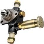
Information injection-pump assembly
ZEXEL
101402-0892
1014020892
ISUZU
8944706501
8944706501
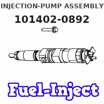
Rating:
Service parts 101402-0892 INJECTION-PUMP ASSEMBLY:
1.
_
5.
AUTOM. ADVANCE MECHANIS
6.
COUPLING PLATE
8.
_
9.
_
11.
Nozzle and Holder
1-15300-120-2
12.
Open Pre:MPa(Kqf/cm2)
18.1{185}
15.
NOZZLE SET
Cross reference number
ZEXEL
101402-0892
1014020892
ISUZU
8944706501
8944706501
Zexel num
Bosch num
Firm num
Name
Calibration Data:
Adjustment conditions
Test oil
1404 Test oil ISO4113 or {SAEJ967d}
1404 Test oil ISO4113 or {SAEJ967d}
Test oil temperature
degC
40
40
45
Nozzle and nozzle holder
105780-8140
Bosch type code
EF8511/9A
Nozzle
105780-0000
Bosch type code
DN12SD12T
Nozzle holder
105780-2080
Bosch type code
EF8511/9
Opening pressure
MPa
17.2
Opening pressure
kgf/cm2
175
Injection pipe
Outer diameter - inner diameter - length (mm) mm 6-2-600
Outer diameter - inner diameter - length (mm) mm 6-2-600
Overflow valve
131424-4920
Overflow valve opening pressure
kPa
127
107
147
Overflow valve opening pressure
kgf/cm2
1.3
1.1
1.5
Tester oil delivery pressure
kPa
157
157
157
Tester oil delivery pressure
kgf/cm2
1.6
1.6
1.6
Direction of rotation (viewed from drive side)
Right R
Right R
Injection timing adjustment
Direction of rotation (viewed from drive side)
Right R
Right R
Injection order
1-3-4-2
Pre-stroke
mm
3.4
3.35
3.45
Beginning of injection position
Drive side NO.1
Drive side NO.1
Difference between angles 1
Cal 1-3 deg. 90 89.5 90.5
Cal 1-3 deg. 90 89.5 90.5
Difference between angles 2
Cal 1-4 deg. 180 179.5 180.5
Cal 1-4 deg. 180 179.5 180.5
Difference between angles 3
Cyl.1-2 deg. 270 269.5 270.5
Cyl.1-2 deg. 270 269.5 270.5
Injection quantity adjustment
Adjusting point
A
Rack position
9.6
Pump speed
r/min
1100
1100
1100
Average injection quantity
mm3/st.
70.2
69.1
71.3
Max. variation between cylinders
%
0
-2
2
Basic
*
Fixing the lever
*
Injection quantity adjustment_02
Adjusting point
-
Rack position
6.9+-0.5
Pump speed
r/min
485
485
485
Average injection quantity
mm3/st.
8.8
7.4
10.2
Max. variation between cylinders
%
0
-14
14
Fixing the rack
*
Remarks
Adjust only variation between cylinders; adjust governor according to governor specifications.
Adjust only variation between cylinders; adjust governor according to governor specifications.
Injection quantity adjustment_03
Adjusting point
C
Rack position
10
Pump speed
r/min
800
800
800
Average injection quantity
mm3/st.
71.6
69.6
73.6
Max. variation between cylinders
%
0
-4
4
Fixing the lever
*
Test data Ex:
Governor adjustment
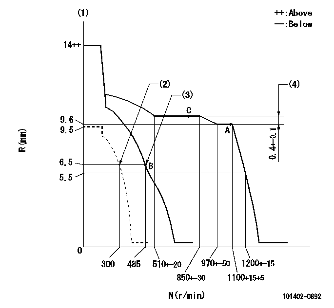
N:Pump speed
R:Rack position (mm)
(1)Target notch: K
(2)Set idle sub-spring
(3)Main spring setting
(4)Rack difference between N = N1 and N = N2
----------
K=8 N1=1100r/min N2=800r/min
----------
----------
K=8 N1=1100r/min N2=800r/min
----------
Speed control lever angle

F:Full speed
I:Idle
(1)Stopper bolt setting
----------
----------
a=1deg+-5deg b=17deg+-5deg
----------
----------
a=1deg+-5deg b=17deg+-5deg
Stop lever angle
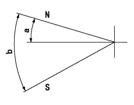
N:Pump normal
S:Stop the pump.
----------
----------
a=4.5deg+-5deg b=53deg+-5deg
----------
----------
a=4.5deg+-5deg b=53deg+-5deg
Timing setting
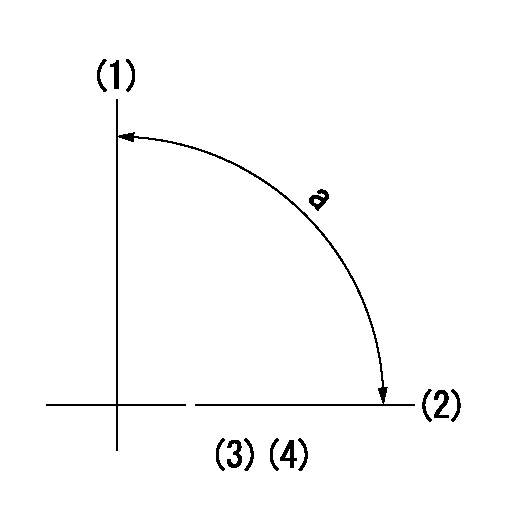
(1)Pump vertical direction
(2)Position of gear mark 'CC' at No 1 cylinder's beginning of injection
(3)B.T.D.C.: aa
(4)-
----------
aa=18deg
----------
a=(90deg)
----------
aa=18deg
----------
a=(90deg)
Information:
CHECK CRANKCASE OIL LEVEL before starting and when refueling. The dipstick has 2 marks, and the distance between them represents 3 quarts. Always check oil with engine stopped and truck on level ground. Use oils meeting the following engine service classification:SC and SD (MS - Motor Severe Oils)CB (Supplement 1 Oils)CC (MIL-L-2104B or MIL-L-46152 Specification Oils)CD or MIL-L-2104CChange engine oil and filters as specified in the Lubrication and Maintenance Charts. CHECK ENGINE COOLANT LEVEL (with engine stopped). Always release cooling system pressure before checking. Fill to the proper level with water, free as possible from scale-forming minerals (not softened water), and rust inhibitor, or a solution of water and a permanent type anti-freeze containing rust inhibitor. It is recommended Caterpillar Coolant System Inhibitor be added to the coolant solution if protection is for temperatures above -20°F (-29°C). It is not necessary to add inhibitor to the coolant solution if protection is for temperatures -20°F (-29°C) and below.Models equipped with sight gauge; coolant should be warm (engine stopped) and coolant should be visible in the sight gauge.
Inhibitor contains alkali. Avoid contact with skin and eyes.
CHECK RADIATOR for dirt and foreign material, fan, water pump and accessory drive belts for cracks, breaks and frayed edges. While checking belts, also check for oil, water and fuel leaks and general appearance of engine and engine compartment. CHECK FUEL SUPPLY: Drain a cupful of fuel from the bottom of the tank to remove water or sediment.Fill fuel tanks after completing a run. Partially filled tanks will collect moisture if the truck is parked for any length of time. Use No. 2D diesel fuel in Caterpillar 1100 Series Diesel Truck Engines. Use No. 1-D diesel fuel in cold temperatures when white smoke must be minimized on start up. Keep fuel clean. Refer to Fuel Specifications for detailed information on fuel selection.
