Information injection-pump assembly
BOSCH
9 400 613 835
9400613835
ZEXEL
101402-0882
1014020882
ISUZU
8943104892
8943104892
Rating:
Service parts 101402-0882 INJECTION-PUMP ASSEMBLY:
1.
_
5.
AUTOM. ADVANCE MECHANIS
6.
COUPLING PLATE
8.
_
9.
_
11.
Nozzle and Holder
1-15300-105-1
12.
Open Pre:MPa(Kqf/cm2)
18.1(185)
15.
NOZZLE SET
Cross reference number
BOSCH
9 400 613 835
9400613835
ZEXEL
101402-0882
1014020882
ISUZU
8943104892
8943104892
Zexel num
Bosch num
Firm num
Name
Calibration Data:
Adjustment conditions
Test oil
1404 Test oil ISO4113 or {SAEJ967d}
1404 Test oil ISO4113 or {SAEJ967d}
Test oil temperature
degC
40
40
45
Nozzle and nozzle holder
105780-8140
Bosch type code
EF8511/9A
Nozzle
105780-0000
Bosch type code
DN12SD12T
Nozzle holder
105780-2080
Bosch type code
EF8511/9
Opening pressure
MPa
17.2
Opening pressure
kgf/cm2
175
Injection pipe
Outer diameter - inner diameter - length (mm) mm 6-2-600
Outer diameter - inner diameter - length (mm) mm 6-2-600
Tester oil delivery pressure
kPa
157
157
157
Tester oil delivery pressure
kgf/cm2
1.6
1.6
1.6
Direction of rotation (viewed from drive side)
Right R
Right R
Injection timing adjustment
Direction of rotation (viewed from drive side)
Right R
Right R
Injection order
1-3-4-2
Pre-stroke
mm
3.4
3.35
3.45
Beginning of injection position
Drive side NO.1
Drive side NO.1
Difference between angles 1
Cal 1-3 deg. 90 89.5 90.5
Cal 1-3 deg. 90 89.5 90.5
Difference between angles 2
Cal 1-4 deg. 180 179.5 180.5
Cal 1-4 deg. 180 179.5 180.5
Difference between angles 3
Cyl.1-2 deg. 270 269.5 270.5
Cyl.1-2 deg. 270 269.5 270.5
Injection quantity adjustment
Adjusting point
A
Rack position
9.2
Pump speed
r/min
1200
1200
1200
Average injection quantity
mm3/st.
67.6
66.1
69.1
Max. variation between cylinders
%
0
-2
2
Basic
*
Fixing the lever
*
Injection quantity adjustment_02
Adjusting point
C
Rack position
6.6+-0.5
Pump speed
r/min
410
410
410
Average injection quantity
mm3/st.
8
6.6
9.4
Max. variation between cylinders
%
0
-14
14
Fixing the rack
*
Test data Ex:
Governor adjustment
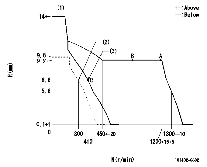
N:Pump speed
R:Rack position (mm)
(1)Target notch: K
(2)Set idle sub-spring
(3)Main spring setting
----------
K=6
----------
----------
K=6
----------
Speed control lever angle
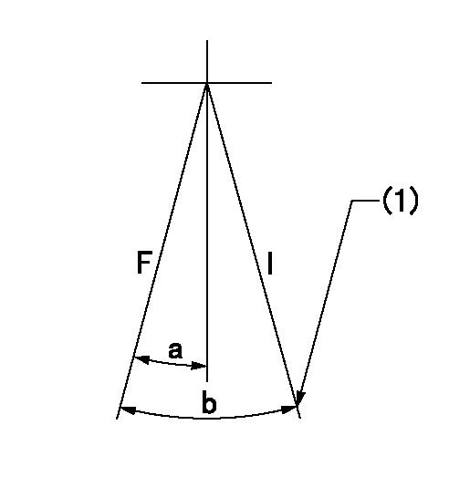
F:Full speed
I:Idle
(1)Stopper bolt setting
----------
----------
a=5deg+-5deg b=21deg+-5deg
----------
----------
a=5deg+-5deg b=21deg+-5deg
Stop lever angle
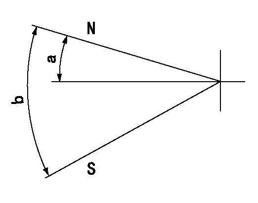
N:Pump normal
S:Stop the pump.
----------
----------
a=4.5deg+-5deg b=53deg+-5deg
----------
----------
a=4.5deg+-5deg b=53deg+-5deg
Timing setting
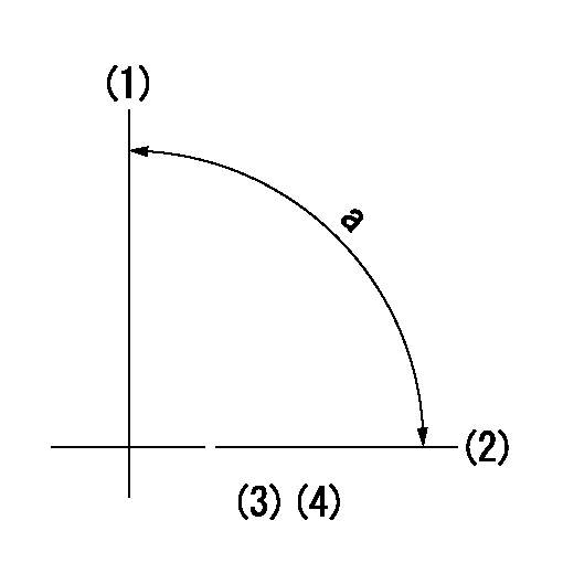
(1)Pump vertical direction
(2)Position of gear mark 'CC' at No 1 cylinder's beginning of injection
(3)B.T.D.C.: aa
(4)-
----------
aa=16deg
----------
a=(90deg)
----------
aa=16deg
----------
a=(90deg)
Information:
The 1100 Series Diesel Truck Engines are direct injection, 4 stroke cycle 90° V8's and have many interchangeable parts.The engine has spin-on, throw-away oil and fuel filters as standard equipment.A positive crankcase ventilation valve is mounted between the rocker arm cover and the air intake pipe. When the engine is running, there is crankcase pressure present to force fumes out through the positive crankcase ventilation valve. Also, the air rushing through the air intake pipe creates a partial vacuum in the positive crankcase ventilation valve which siphons fumes from the engine, crankcase and rocker arm covers. The fumes then are introduced into the air induction system and mixed with the air going to the cylinders on each intake stroke.There is a fuel injection pump for each cylinder that meters and pumps fuel under high pressure to an injection nozzle located in each cylinder of the engine.An automatic timing system is mounted on the front of the engine camshaft. The automatic timing system helps assure correct combustion and performance no matter what engine RPM or gear range the driver chooses. Good fuel economy, easy starting, low noise level and minimum smoke are a few of the benefits this system provides.A governor maintains the engine RPM selected by the operator. Later 1100 Series Engines have a hydraulic governor mounted on the rear of the fuel injection pump housing. This governor maintains control of the fuel rack (which determines the amount of fuel being injected into the cylinders).The engines are of the overhead valve design and have one inlet and one exhaust valve for each cylinder. The camshaft, geared and timed to the crankshaft, actuates rocker arms and valves through mechanical lifters and push rods. There is a single rocker arm shaft for each head. The shaft is mounted in the aluminum support, spacing the rocker arms. The entire rocker arm assembly can be removed and installed as a unit.Lubrication for the engine is supplied by a six eccentric lobe oil pump, housed in the timing gear cover. The lubricating oil is cooled and filtered. By-pass valves in the pump cover, oil cooler and oil filters provide unrestricted oil flow if oil filters or cooler becomes clogged.The cooling system consists of a belt driven centrifugal pump, two thermostats on the inlet side of the water pump which regulate engine coolant temperature, an oil cooler and a radiator incorporating a shunt system.Efficiency of emission controls and engine performance depends on adherence to proper operation and maintenance recommendations, and use of recommended fuels and lubrication oils. Major adjustments and repair should be entrusted to your authorized dealer. Follow the recommended maintenance schedule with special emphasis on fuel injectors, air cleaner, positive crankcase ventilation valve and high and low idle adjustment. The governor high and low idle adjustments should be made by an authorized dealer.
