Information injection-pump assembly
BOSCH
9 400 613 832
9400613832
ZEXEL
101402-0840
1014020840
ISUZU
8944547620
8944547620
Rating:
Service parts 101402-0840 INJECTION-PUMP ASSEMBLY:
1.
_
5.
AUTOM. ADVANCE MECHANIS
6.
COUPLING PLATE
8.
_
9.
_
10.
NOZZLE AND HOLDER ASSY
11.
Nozzle and Holder
5-15300-092-0
12.
Open Pre:MPa(Kqf/cm2)
14.7(150)
13.
NOZZLE-HOLDER
15.
NOZZLE SET
Cross reference number
BOSCH
9 400 613 832
9400613832
ZEXEL
101402-0840
1014020840
ISUZU
8944547620
8944547620
Zexel num
Bosch num
Firm num
Name
101402-0840
9 400 613 832
8944547620 ISUZU
INJECTION-PUMP ASSEMBLY
4BB1 * K
4BB1 * K
Calibration Data:
Adjustment conditions
Test oil
1404 Test oil ISO4113 or {SAEJ967d}
1404 Test oil ISO4113 or {SAEJ967d}
Test oil temperature
degC
40
40
45
Nozzle and nozzle holder
105780-8140
Bosch type code
EF8511/9A
Nozzle
105780-0000
Bosch type code
DN12SD12T
Nozzle holder
105780-2080
Bosch type code
EF8511/9
Opening pressure
MPa
17.2
Opening pressure
kgf/cm2
175
Injection pipe
Outer diameter - inner diameter - length (mm) mm 6-2-600
Outer diameter - inner diameter - length (mm) mm 6-2-600
Tester oil delivery pressure
kPa
157
157
157
Tester oil delivery pressure
kgf/cm2
1.6
1.6
1.6
Direction of rotation (viewed from drive side)
Right R
Right R
Injection timing adjustment
Direction of rotation (viewed from drive side)
Right R
Right R
Injection order
1-3-4-2
Pre-stroke
mm
3.6
3.55
3.65
Beginning of injection position
Drive side NO.1
Drive side NO.1
Difference between angles 1
Cal 1-3 deg. 90 89.5 90.5
Cal 1-3 deg. 90 89.5 90.5
Difference between angles 2
Cal 1-4 deg. 180 179.5 180.5
Cal 1-4 deg. 180 179.5 180.5
Difference between angles 3
Cyl.1-2 deg. 270 269.5 270.5
Cyl.1-2 deg. 270 269.5 270.5
Injection quantity adjustment
Adjusting point
A
Rack position
9.7
Pump speed
r/min
700
700
700
Average injection quantity
mm3/st.
53.9
52.9
54.9
Max. variation between cylinders
%
0
-2
2
Basic
*
Fixing the lever
*
Injection quantity adjustment_02
Adjusting point
B
Rack position
9.2
Pump speed
r/min
975
975
975
Average injection quantity
mm3/st.
48.3
46.3
50.3
Max. variation between cylinders
%
0
-4
4
Fixing the lever
*
Injection quantity adjustment_03
Adjusting point
C
Rack position
7.7+-0.5
Pump speed
r/min
350
350
350
Average injection quantity
mm3/st.
8.9
7.5
10.3
Max. variation between cylinders
%
0
-14
14
Fixing the rack
*
Test data Ex:
Governor adjustment
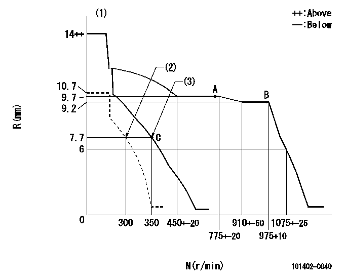
N:Pump speed
R:Rack position (mm)
(1)Target notch: K
(2)Set idle sub-spring
(3)Main spring setting
----------
K=7
----------
----------
K=7
----------
Speed control lever angle

F:Full speed
I:Idle
(1)Stopper bolt setting
----------
----------
a=3deg+-5deg b=18deg+-5deg
----------
----------
a=3deg+-5deg b=18deg+-5deg
Stop lever angle

N:Pump normal
S:Stop the pump.
----------
----------
a=4.5deg+-5deg b=53deg+-5deg
----------
----------
a=4.5deg+-5deg b=53deg+-5deg
Timing setting

(1)Pump vertical direction
(2)Position of gear mark 'CC' at No 1 cylinder's beginning of injection
(3)B.T.D.C.: aa
(4)-
----------
aa=18deg
----------
a=(90deg)
----------
aa=18deg
----------
a=(90deg)
Information:
Crankcase Lubricating Oil
The Lubrication and Maintenance Charts list the normal oil change periods as determined by fuel sulphur content. (Make an initial oil change after the first 500 miles of operation for reconditioned engines.)Use oils which meet Engine Service classification CD or MIL-L-2104C. These are additive-type oils that have been approved for use in Caterpillar Diesel Engines. Diesel Engine Crankcase
Check oil level daily before starting engine and when refueling. Check with the engine either running or stopped as indicated on the oil level gauge. Add oil when the level drops to the add oil mark. Drain the crankcase every 10,000 miles while engine is warm and stopped. If equipped with a 13 qt. supplemental filter system the normal interval can be extended to 15,000 miles. Install drain plug. Diesel Engine Crankcase Lubricating Oil Filter
Change filter element every 10,000 miles. Drain the filter housing by removing drain plug. Loosen bolt on the cover and remove the housing and filter element. Inspect seal and install a new one if necessary. Wash the inside of the filter housing and install a new Caterpillar filter element. After draining crankcase remove filter cap and refill. See page 15 for quantity. Start engine and check for oil leaks at drain plug and filter housing. Diesel Engine Crankcase Breather
Remove breather tube cover and element. Wash with clean solvent or diesel fuel at each oil change period. Inspect seal and replace if necessary. Lubricating Grease
Use Multipurpose-type Grease which contains both 3 to 5% molybdenum disulfide conforming to MIL-M-7866, and a suitable corrosion inhibitor. NLGI No. 2 Grade is suitable for most temperatures. NLGI No. 1 or No. 0 are suitable for extremely low temperatures.Always clean fittings before lubricating.Fan Pulley Bearing
Lubricate every 10,000 miles. Lubricate through fitting until grease appears at relief fitting on front of fan hub. Wipe off excess grease. Water Pump Bearing
Lubricate every 10,000 miles. Lubricate through fitting until lubricant appears at relief fitting. Earlier engines have no relief fitting. Excess lubricant will appear at end of water pump shaft. Tachometer Drive
Lubricate every 10,000 miles. Remove plug. Install grease fitting and apply one stroke of lubricant through fitting.
Have questions with 101402-0840?
Group cross 101402-0840 ZEXEL
Isuzu
101402-0840
9 400 613 832
8944547620
INJECTION-PUMP ASSEMBLY
4BB1
4BB1