Information injection-pump assembly
BOSCH
9 400 610 169
9400610169
ZEXEL
101402-0732
1014020732
ISUZU
8944206622
8944206622
Rating:
Service parts 101402-0732 INJECTION-PUMP ASSEMBLY:
1.
_
5.
AUTOM. ADVANCE MECHANIS
6.
COUPLING PLATE
8.
_
9.
_
11.
Nozzle and Holder
1-15300-120-2
12.
Open Pre:MPa(Kqf/cm2)
18.1{185}
15.
NOZZLE SET
Cross reference number
BOSCH
9 400 610 169
9400610169
ZEXEL
101402-0732
1014020732
ISUZU
8944206622
8944206622
Zexel num
Bosch num
Firm num
Name
9 400 610 169
8944206622 ISUZU
INJECTION-PUMP ASSEMBLY
4BD1-T * K 14BC PE4A,5A, PE
4BD1-T * K 14BC PE4A,5A, PE
Calibration Data:
Adjustment conditions
Test oil
1404 Test oil ISO4113 or {SAEJ967d}
1404 Test oil ISO4113 or {SAEJ967d}
Test oil temperature
degC
40
40
45
Nozzle and nozzle holder
105780-8140
Bosch type code
EF8511/9A
Nozzle
105780-0000
Bosch type code
DN12SD12T
Nozzle holder
105780-2080
Bosch type code
EF8511/9
Opening pressure
MPa
17.2
Opening pressure
kgf/cm2
175
Injection pipe
Outer diameter - inner diameter - length (mm) mm 6-2-600
Outer diameter - inner diameter - length (mm) mm 6-2-600
Tester oil delivery pressure
kPa
157
157
157
Tester oil delivery pressure
kgf/cm2
1.6
1.6
1.6
Direction of rotation (viewed from drive side)
Right R
Right R
Injection timing adjustment
Direction of rotation (viewed from drive side)
Right R
Right R
Injection order
1-3-4-2
Pre-stroke
mm
3.4
3.35
3.45
Beginning of injection position
Drive side NO.1
Drive side NO.1
Difference between angles 1
Cal 1-3 deg. 90 89.5 90.5
Cal 1-3 deg. 90 89.5 90.5
Difference between angles 2
Cal 1-4 deg. 180 179.5 180.5
Cal 1-4 deg. 180 179.5 180.5
Difference between angles 3
Cyl.1-2 deg. 270 269.5 270.5
Cyl.1-2 deg. 270 269.5 270.5
Injection quantity adjustment
Adjusting point
A
Rack position
10
Pump speed
r/min
1100
1100
1100
Average injection quantity
mm3/st.
81
79.5
82.5
Max. variation between cylinders
%
0
-2
2
Basic
*
Fixing the lever
*
Injection quantity adjustment_02
Adjusting point
B
Rack position
6.5+-0.5
Pump speed
r/min
400
400
400
Average injection quantity
mm3/st.
8
6.6
9.4
Max. variation between cylinders
%
0
-14
14
Fixing the rack
*
Test data Ex:
Governor adjustment
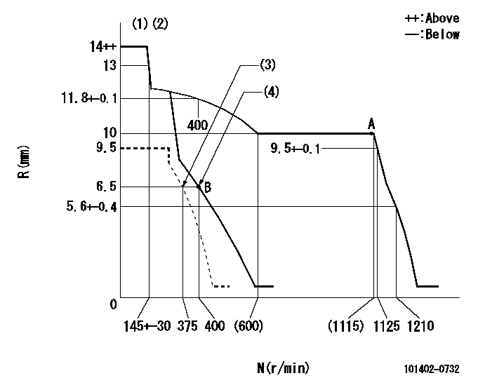
N:Pump speed
R:Rack position (mm)
(1)Target notch: K
(2)Tolerance for racks not indicated: +-0.05mm.
(3)Set idle sub-spring
(4)Main spring setting
----------
K=5
----------
----------
K=5
----------
Speed control lever angle
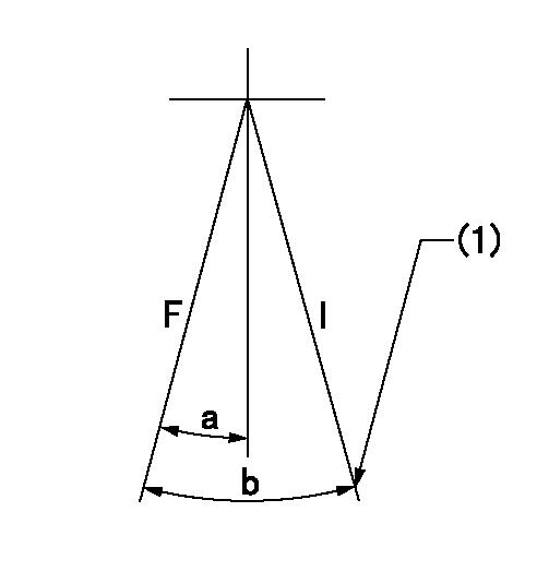
F:Full speed
I:Idle
(1)Stopper bolt setting
----------
----------
a=0deg+-5deg b=22deg+-5deg
----------
----------
a=0deg+-5deg b=22deg+-5deg
Stop lever angle

N:Pump normal
S:Stop the pump.
(1)Normal
----------
----------
a=19deg+-5deg b=53deg+-5deg
----------
----------
a=19deg+-5deg b=53deg+-5deg
Timing setting
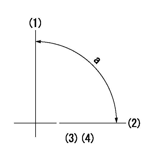
(1)Pump vertical direction
(2)Position of gear mark 'CC' at No 1 cylinder's beginning of injection
(3)B.T.D.C.: aa
(4)-
----------
aa=18deg
----------
a=(90deg)
----------
aa=18deg
----------
a=(90deg)
Information:
Introduction
The problem that is identified below does not have a known permanent solution. Until a permanent solution is known, use the solution that is identified below.Problem
Diesel exhaust fluid may begin to leak from the 421-6842 Control Valve As due to breakage of the valve stem.
Illustration 1 g03774942
Location of valve assemblySolution
In order to fix the valve assembly leakage, rework the hose installation and replace the valve if the valve stem has broken. Refer to the following ""Rework Procedure"".Required Parts
Table 1
Required Parts
Item Qty Part Number Description
1 1 421-6842 Control Valve As (1)
2 2 132-5789 Clip
3 2 3S-2093 Cable Strap
( 1 ) If neededRework Procedure
Check the diesel exhaust fluid leakage from valve assembly (1). If there is no leakage, skip Steps 2 and 3. If there is leakage present, perform the following Steps 1 through 6.
Illustration 2 g03774935
(1) 421-6842 Control Valve As (4) 8M-2773 Clip or 067-2551 Clip (depending on sales model) (5) 8T-4137 Bolt (6) 8T-4121 Hard Washer (7) 6S-8620 Hose Clamp
Remove two clips (4), two bolts (5), and two washers (6) .Note: Retain the bolts and washers for reuse when installing the new clips.
Remove valve assembly (1) and two clamps (7) .
Attach the two hoses to new valve assembly (1). Secure by tightening the clamps to a torque of 1.4 0.3 N m (12.4 2.7 lb in).Note: Insert the hose up to the root of the valve tube.Note: Place the clamp on the straight portion of the hose by the bead of the valve tube.
Illustration 3 g03774975
(1) 421-6842 Control Valve As (3) 3S-2093 Cable Strap (5) 8T-4137 Bolt (6) 8T-4121 Hard Washer (A) 90 degree angle
Install two new clips (2) and secure with bolts (5) and washers (6) on the mounting boss.
Tighten bolts (5) to a torque of 55 10 N m (40.6 7.8 lb ft).
Secure both hoses to clips (2) using straps (3). Ensure that both hoses are straight against valve assembly (1) .Note: The clips must be attached at a 90 degree angle to the valve assembly. Refer to Illustration 3.Note: Do not apply a twisting force on the valve assembly when securing the hoses.Note: Do not deform the hoses when tightening the straps.
