Information injection-pump assembly
ZEXEL
101402-0580
1014020580
ISUZU
8941415260
8941415260

Rating:
Cross reference number
ZEXEL
101402-0580
1014020580
ISUZU
8941415260
8941415260
Zexel num
Bosch num
Firm num
Name
Calibration Data:
Adjustment conditions
Test oil
1404 Test oil ISO4113 or {SAEJ967d}
1404 Test oil ISO4113 or {SAEJ967d}
Test oil temperature
degC
40
40
45
Nozzle and nozzle holder
105780-8140
Bosch type code
EF8511/9A
Nozzle
105780-0000
Bosch type code
DN12SD12T
Nozzle holder
105780-2080
Bosch type code
EF8511/9
Opening pressure
MPa
17.2
Opening pressure
kgf/cm2
175
Injection pipe
Outer diameter - inner diameter - length (mm) mm 6-2-600
Outer diameter - inner diameter - length (mm) mm 6-2-600
Tester oil delivery pressure
kPa
157
157
157
Tester oil delivery pressure
kgf/cm2
1.6
1.6
1.6
Direction of rotation (viewed from drive side)
Right R
Right R
Injection timing adjustment
Direction of rotation (viewed from drive side)
Right R
Right R
Injection order
1-3-4-2
Pre-stroke
mm
3.6
3.55
3.65
Beginning of injection position
Drive side NO.1
Drive side NO.1
Difference between angles 1
Cal 1-3 deg. 90 89.5 90.5
Cal 1-3 deg. 90 89.5 90.5
Difference between angles 2
Cal 1-4 deg. 180 179.5 180.5
Cal 1-4 deg. 180 179.5 180.5
Difference between angles 3
Cyl.1-2 deg. 270 269.5 270.5
Cyl.1-2 deg. 270 269.5 270.5
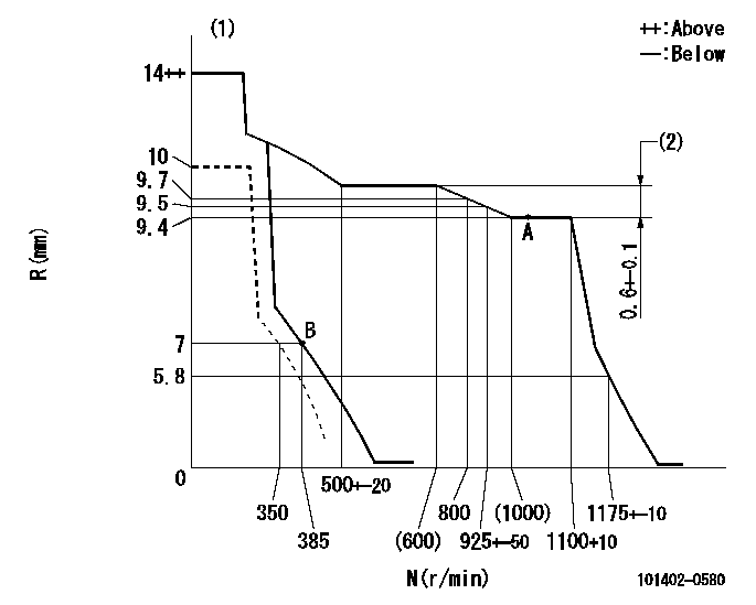
Injection quantity adjustment
Adjusting point
A
Rack position
9.4
Pump speed
r/min
1000
1000
1000
Average injection quantity
mm3/st.
56.5
55.5
57.5
Max. variation between cylinders
%
0
-2
2
Basic
*
Fixing the lever
*
Injection quantity adjustment_02
Adjusting point
B
Rack position
7.2+-0.5
Pump speed
r/min
385
385
385
Average injection quantity
mm3/st.
11.6
10.2
13
Max. variation between cylinders
%
0
-14
14
Fixing the rack
*
Remarks
Adjust only variation between cylinders; adjust governor according to governor specifications.
Adjust only variation between cylinders; adjust governor according to governor specifications.
Test data Ex:
Governor adjustment
N:Pump speed
R:Rack position (mm)
(1)Notch fixed: K
(2)Rack difference between N = N1 and N = N2
----------
K=7 N1=1000r/min N2=550r/min
----------
----------
K=7 N1=1000r/min N2=550r/min
----------
Speed control lever angle
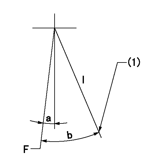
F:Full speed
I:Idle
(1)Stopper bolt setting
----------
----------
a=(10deg)+-5deg b=(27deg)+-5deg
----------
----------
a=(10deg)+-5deg b=(27deg)+-5deg
Stop lever angle

N:Pump normal
S:Stop the pump.
----------
----------
a=19deg+-5deg b=53deg+-5deg
----------
----------
a=19deg+-5deg b=53deg+-5deg
Timing setting

(1)Pump vertical direction
(2)Position of gear mark 'CC' at No 1 cylinder's beginning of injection
(3)B.T.D.C.: aa
(4)-
----------
aa=19deg
----------
a=(90deg)
----------
aa=19deg
----------
a=(90deg)
Information:
Introduction
This Special Instruction is intended for the installation of the 366-9748 Injector Wiring Harness Kit . The 366-9748 Injector Wiring Harness Kit can be used to repair TPI connectors. TPI connectors can be found on HEUI injectors, variable valve actuators, and Cat Brakes.Removal of the Connector From the Wire Harness
Table 1
Required Tools
Tool Part Number Part Description Qty
A 9S-9150 Terminal Crimp Tool As 1
B 9U-6070
or Heat Gun Gp
(110V) 1
9U-6072 Heat Gun Gp (220 V) The following steps will remove the connector for an injector from the wire harness that is under the valve mechanism cover.
Illustration 1 g01035448
(1) Side "A" of the connector (2) Side "B" of the connectorNote: Side "A" or side "1" of the connector is the output signal wire from the ECM. Side"B" or side "2" of the connector is the sensor return.
Identify side "A" of the connector and identify side "B" of the connector.
Mark each wire on the wire harness before the wires are cut. Most connectors will have the label of an "A" and a "B". Some connectors may have a "1" and a "2" that is on the connector. The label with a "1" will be an "A". The label with a "2" will be a "B".
Illustration 2 g01034438
Connector that is cut from the wire harness (3) Wire on side "A" of the connector (4) Wire on side "B" of the connector
Cut wire (3) at a distance of 45 mm (1.8 inch).
Cut wire (4) at a distance of 40 mm (1.6 inch).
Illustration 3 g01034450
(5) Wire from the harness for side "B" on the connector (6) Wire from the harness for side "A" on the connectorNote: The wires on the old connector are cut to length so that the wires on the wire harness to the new connector will match up. The proper length will help in matching the harness wires to the wires on the new connector wires.
Discard the connector.Installation Procedure for the Connector
Use Tool (A) to strip the plastic off wires (5) and (6) at a distance of 5 mm (0.19 inch).
Illustration 4 g01034451
Connecting the connector to the wire harness (5) Wire from the harness for side "B" on the connector (6) Wire from the harness for side "A" on the connector (7) Heat shrink tube (8) Butt splice on wire (4) that is on side "B" of the connector (9) Butt splice on wire (3) that is on side "A" of the connector
Use the heat shrink tubes from 366-9748 Injector Wiring Harness Kit . Slide the heat shrink tubes toward the connector in order to expose the butt splices.
Take wire (5) and slide wire (5) in the butt splice (8).
Take wire (6) and slide wire (6) in the butt splice (9).
Illustration 5 g01035814
Illustration 6 g01034452
(8) Butt splice on wire (4) that is on side "B" of the connector (9) Butt splice on wire (3) that is on side "A" of the connector
Use Tool