Information injection-pump assembly
ZEXEL
101402-0381
1014020381
ISUZU
5156012681
5156012681
Rating:
Cross reference number
ZEXEL
101402-0381
1014020381
ISUZU
5156012681
5156012681
Zexel num
Bosch num
Firm num
Name
Calibration Data:
Adjustment conditions
Test oil
1404 Test oil ISO4113 or {SAEJ967d}
1404 Test oil ISO4113 or {SAEJ967d}
Test oil temperature
degC
40
40
45
Nozzle and nozzle holder
105780-8140
Bosch type code
EF8511/9A
Nozzle
105780-0000
Bosch type code
DN12SD12T
Nozzle holder
105780-2080
Bosch type code
EF8511/9
Opening pressure
MPa
17.2
Opening pressure
kgf/cm2
175
Injection pipe
Outer diameter - inner diameter - length (mm) mm 6-2-600
Outer diameter - inner diameter - length (mm) mm 6-2-600
Tester oil delivery pressure
kPa
157
157
157
Tester oil delivery pressure
kgf/cm2
1.6
1.6
1.6
Direction of rotation (viewed from drive side)
Right R
Right R
Injection timing adjustment
Direction of rotation (viewed from drive side)
Right R
Right R
Injection order
1-3-4-2
Pre-stroke
mm
3.6
3.55
3.65
Beginning of injection position
Drive side NO.1
Drive side NO.1
Difference between angles 1
Cal 1-3 deg. 90 89.5 90.5
Cal 1-3 deg. 90 89.5 90.5
Difference between angles 2
Cal 1-4 deg. 180 179.5 180.5
Cal 1-4 deg. 180 179.5 180.5
Difference between angles 3
Cyl.1-2 deg. 270 269.5 270.5
Cyl.1-2 deg. 270 269.5 270.5
Injection quantity adjustment
Adjusting point
A
Rack position
9.3
Pump speed
r/min
1000
1000
1000
Average injection quantity
mm3/st.
55.2
54.2
56.2
Max. variation between cylinders
%
0
-2
2
Basic
*
Fixing the lever
*
Injection quantity adjustment_02
Adjusting point
B
Rack position
7.7+-0.5
Pump speed
r/min
385
385
385
Average injection quantity
mm3/st.
10
8.6
11.4
Max. variation between cylinders
%
0
-14
14
Fixing the rack
*
Test data Ex:
Governor adjustment
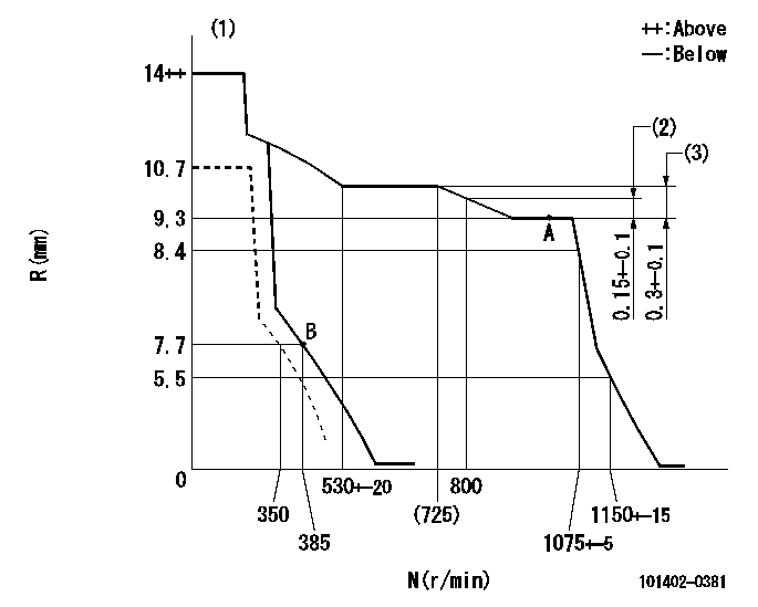
N:Pump speed
R:Rack position (mm)
(1)Target notch: K
(2)Rack difference between N = N1 and N = N2
(3)Rack difference between N = N3 and N = N4
----------
K=10 N1=1000r/min N2=800r/min N3=1000r/min N4=600r/min
----------
----------
K=10 N1=1000r/min N2=800r/min N3=1000r/min N4=600r/min
----------
Speed control lever angle
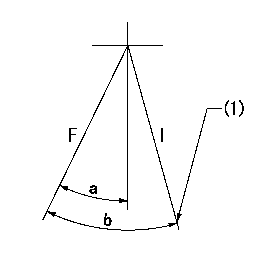
F:Full speed
I:Idle
(1)Stopper bolt setting
----------
----------
a=12deg+-5deg b=28deg+-5deg
----------
----------
a=12deg+-5deg b=28deg+-5deg
Stop lever angle

N:Pump normal
S:Stop the pump.
----------
----------
a=19deg+-5deg b=53deg+-5deg
----------
----------
a=19deg+-5deg b=53deg+-5deg
Timing setting

(1)Pump vertical direction
(2)Position of gear mark 'CC' at No 1 cylinder's beginning of injection
(3)B.T.D.C.: aa
(4)-
----------
aa=18deg
----------
a=(90deg)
----------
aa=18deg
----------
a=(90deg)
Information:
Fuel Tank Drain
Fuel tank drains are used to drain water and sediment from the fuel tank daily. The drain must be located on the lowest part of the fuel tank where the containments collect.Note: Daily draining of water and sediment from the fuel tank has been a standard maintenance requirement for decades.Advanced Tank Breather Filter
Preventing short fuel system life by keeping dust from entering the fuel tank.Water Separators
Water separators are required to remove large quantities of latent water from the fuel.Primary Fuel Filters
Primary fuel filters are required to remove large abrasives from the fuel supply and prevent premature clogging of the 4-micron secondary filters from excessive debris.Secondary Fuel Filters
Series filtration more than doubles wear life over single filtration.Electronic Unit Injectors (EUI)
An adequate fuel supply pressure is essential to prevent cavitation of internal injector components due to incomplete fuel fill.Major Factors Which Negatively Affect Fuel System Wear
Abrasive Contaminants
Increased injection pressure acting on the same level of abrasive contaminants in the fuel results in accelerated injector abrasive wear. This abrasive wear cannot be eliminated by using improved materials or processes. Abrasive wear only can be reduced by removing abrasives from the fuel. Solution
Single or series High Efficiency fuel filters and/or bulk fuel filter/water coalescer.Water in Fuel
An excessive amount of latent water in the fuel is a key cause of injector failure. Water has inadequate film strength to prevent metal-to-metal contact between the plunger and barrel, resulting in plunger scuffing or seizure. Water can be effectively by the use and regular maintenance of a water separator or bulk fuel filter/water coalescer. Removal of excess latent water is essential to prevent scuffing with the upcoming injection pressure increases and subsequent hydraulic loading of internal injector parts.Solution
Proper maintenance of fuel tank drains, water separators and/or use of a bulk fuel filter/water coalescer.Excessive Fuel Temperature
Increasing fuel temperatures reduces fuel viscosity and resultant fuel film strength. Reduced film strength increases the probability of injector plunger and barrel scuffing or seizure. Limiting the maximum fuel temperature will become even more critical with the increase of use if low sulfur fuel which has a lower film strength and common rail fuel systems which run elevated fuel temperatures. Fuel temperatures also play in diesel and biodiesel fuel degradation.Solution
Properly maintain fuel filters and fuel coolers where needed. Ensure proper consideration for materials used in fuel coolers as zinc, copper, lead, and tin can have adverse effects on fuel degradation.Customer Maintenance Practices
Fuel system performance, sophistication, and complexity continue to increase at a rapid pace. It is more important than ever for the user to maintain fuel filters in order to prevent filter restriction and the problems caused by low fuel pressure. It is also important to use quality Advanced Efficiency filters in order to trap and hold microscopic abrasive debris, which causes accelerated wear in modern fuel systems.C7 and C9 HEUI Fuel System Diagram
Note: The following illustration identifies components that may be included in many different arrangements. Refer to the Service Information System (SIS) for the correct components for the