Information injection-pump assembly
ZEXEL
101402-0200
1014020200
ISUZU
5156008513
5156008513
Rating:
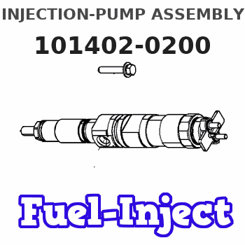
Service parts 101402-0200 INJECTION-PUMP ASSEMBLY:
1.
_
5.
AUTOM. ADVANCE MECHANIS
6.
COUPLING PLATE
8.
_
9.
_
11.
Nozzle and Holder
5-15300-089-1
12.
Open Pre:MPa(Kqf/cm2)
18.1{185}
15.
NOZZLE SET
Cross reference number
ZEXEL
101402-0200
1014020200
ISUZU
5156008513
5156008513
Zexel num
Bosch num
Firm num
Name
101402-0200
5156008513 ISUZU
INJECTION-PUMP ASSEMBLY
4BB1 * K 14BC PE4A,5A, PE
4BB1 * K 14BC PE4A,5A, PE
Calibration Data:
Adjustment conditions
Test oil
1404 Test oil ISO4113 or {SAEJ967d}
1404 Test oil ISO4113 or {SAEJ967d}
Test oil temperature
degC
40
40
45
Nozzle and nozzle holder
105780-8140
Bosch type code
EF8511/9A
Nozzle
105780-0000
Bosch type code
DN12SD12T
Nozzle holder
105780-2080
Bosch type code
EF8511/9
Opening pressure
MPa
17.2
Opening pressure
kgf/cm2
175
Injection pipe
Outer diameter - inner diameter - length (mm) mm 6-2-600
Outer diameter - inner diameter - length (mm) mm 6-2-600
Tester oil delivery pressure
kPa
157
157
157
Tester oil delivery pressure
kgf/cm2
1.6
1.6
1.6
Direction of rotation (viewed from drive side)
Right R
Right R
Injection timing adjustment
Direction of rotation (viewed from drive side)
Right R
Right R
Injection order
1-3-4-2
Pre-stroke
mm
3.6
3.55
3.65
Beginning of injection position
Drive side NO.1
Drive side NO.1
Difference between angles 1
Cal 1-3 deg. 90 89.5 90.5
Cal 1-3 deg. 90 89.5 90.5
Difference between angles 2
Cal 1-4 deg. 180 179.5 180.5
Cal 1-4 deg. 180 179.5 180.5
Difference between angles 3
Cyl.1-2 deg. 270 269.5 270.5
Cyl.1-2 deg. 270 269.5 270.5
Injection quantity adjustment
Adjusting point
A
Rack position
9.5
Pump speed
r/min
800
800
800
Average injection quantity
mm3/st.
57.2
56.2
58.2
Max. variation between cylinders
%
0
-2
2
Basic
*
Fixing the lever
*
Injection quantity adjustment_02
Adjusting point
B
Rack position
9.5
Pump speed
r/min
1000
1000
1000
Average injection quantity
mm3/st.
59.7
57.7
61.7
Max. variation between cylinders
%
0
-4
4
Fixing the lever
*
Injection quantity adjustment_03
Adjusting point
C
Rack position
7.4+-0.5
Pump speed
r/min
350
350
350
Average injection quantity
mm3/st.
10
8.6
11.4
Max. variation between cylinders
%
0
-14
14
Fixing the rack
*
Remarks
Adjust only variation between cylinders; adjust governor according to governor specifications.
Adjust only variation between cylinders; adjust governor according to governor specifications.
Test data Ex:
Governor adjustment
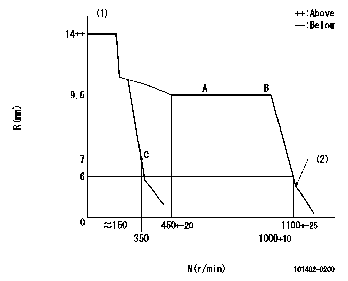
N:Pump speed
R:Rack position (mm)
(1)Target notch: K
(2)Idle sub spring setting: L1.
----------
K=6 L1=6-0.5mm
----------
----------
K=6 L1=6-0.5mm
----------
Speed control lever angle
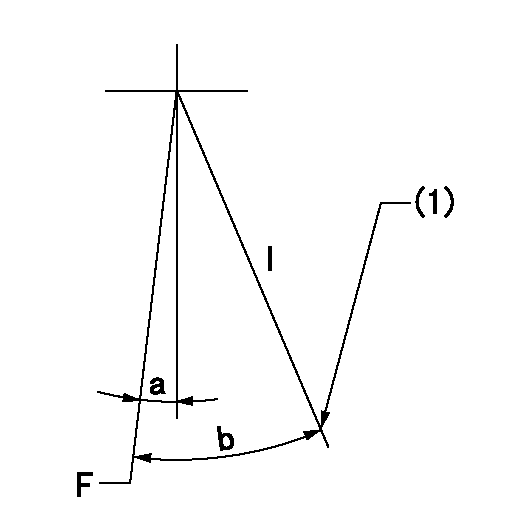
F:Full speed
I:Idle
(1)Stopper bolt setting
----------
----------
a=1deg+-5deg b=21deg+-5deg
----------
----------
a=1deg+-5deg b=21deg+-5deg
Stop lever angle
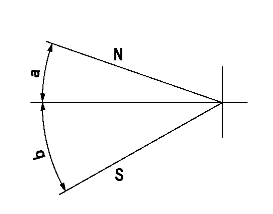
N:Pump normal
S:Stop the pump.
----------
----------
a=(19deg) b=(34deg)
----------
----------
a=(19deg) b=(34deg)
Timing setting
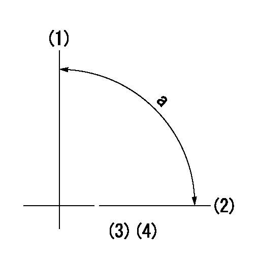
(1)Pump vertical direction
(2)Position of gear mark 'CC' at No 1 cylinder's beginning of injection
(3)-
(4)-
----------
----------
a=(90deg)
----------
----------
a=(90deg)
Information:
Parts Location
Illustration 2 g01666016
Exploded view (1) 304-1120 Diesel Particulate Filter Gp (2) 308-4936 Bracket As (3) 308-4941 Clamp As (4) 277-4718 Clamp As (5) 3B-4508 Lockwasher (6) 5P-8245 Hard Washer (7) 6V-8149 Nut (8) 6V-3823 Bolt (9) 8T-4121 Hard Washer (10) 8T-4196 Bolt Installation Procedure
Diesel Particulate Filter Installation
Illustration 3 g01667275
(11) 241-9265 Muffler Clamp (16) Muffler Assembly (17) Bracket Assembly (18) Support Assembly (19) Exhaust Pipe Assembly (20) Clamp (21) Pipe Assembly (22) Bolt (23) Hard Washer (24) Bolt (25) Washer (26) Plate (27) Bolt (28) Hard Washer (29) Plate
Illustration 4 g01601993
(2) 308-4936 Bracket As (22) Bolt (23) Hard washer (24) Bolt (25) Washer (27) Bolt (28) Hard washer
Remove the existing muffler assembly (16) and bracket assembly (17). Set aside exhaust pipe assembly (19), clamp (20), three bolts (22), three hard washers (23), two bolts (24), two washers (25), three bolts (27), and three hard washers (28). These parts will be reused in later steps.
Reuse three bolts (22), and three hard washers (23) to secure the new 308-4936 Bracket As (2) to existing support assembly (18) .
Reuse two bolts (24), and two washers (25) to secure bracket assembly (2) to existing plate (26) .
Reuse three bolts (27), and three hard washers (28) to secure bracket assembly (2) to existing plate (29) .
Illustration 5 g01602054
(3) 308-4941 Clamp As (9) 8T-4121 Hard Washer (10) 8T-4196 Bolt
Install the two new 308-4941 Clamp As (3) by using four 8T-4196 Bolts (10), and 8T-4121 Hard Washers (9). Loosely secure the four bolts so that the clamp assemblies are adjustable. Refer to Illustration 5.
Illustration 6 g01602115
(1) 304-1120 Diesel Particulate Filter Gp (30) Inlet module tube
Install the new 304-1120 Diesel Particulate Filter Gp (1) on top of clamp assemblies (3). Make sure that inlet module tube (30) fits into existing pipe assembly (21). Use a new 241-9265 Muffler Clamp (11) to secure the joint. Refer to Illustration 6.
Illustration 7 g01601954
(4) 277-4718 Clamp As (5) 3B-4508 Lockwasher (6) 5P-8245 Hard Washer (7) 6V-8149 Nut (8) 6V-3823 Bolt (31) Outlet module tube
Once you have the pipe assembly installed properly, tighten the two bottom clamp assemblies (3). Install the new 277-4718 Clamp As (4) by using the four 5P-8245 Hard Washers (6), and four 6V-3823 Bolts (8). Use the four 3B-4508 Lockwashers (5), and four 6V-8149 Nuts (7) on the clamp assembly (3) side. Refer to Illustration 7.
Install the existing exhaust pipe assembly (19) to the outlet module tube of the diesel particulate filter. Secure the connection with existing clamp (20) .
Reconnect the drain lines.Exhaust Monitor Installation
Refer to Special Instruction, REHS5606, "Installation and Operation of the Caterpillar Diesel Particulate Filter (DPF) and the Diagnostic Module for Non-Road Machine Applications (Non-California Applications)" for information regarding the installation and the operation of the exhaust monitor.The exhaust
Have questions with 101402-0200?
Group cross 101402-0200 ZEXEL
Isuzu
101402-0200
5156008513
INJECTION-PUMP ASSEMBLY
4BB1
4BB1
