Information injection-pump assembly
ZEXEL
101402-0120
1014020120
ISUZU
5156006813
5156006813
Rating:
Service parts 101402-0120 INJECTION-PUMP ASSEMBLY:
1.
_

5.
AUTOM. ADVANCE MECHANIS
6.
COUPLING PLATE
8.
_
9.
_
10.
NOZZLE AND HOLDER ASSY
11.
Nozzle and Holder
5-15300-065-1
12.
Open Pre:MPa(Kqf/cm2)
13.
NOZZLE-HOLDER
15.
NOZZLE SET
Cross reference number
ZEXEL
101402-0120
1014020120
ISUZU
5156006813
5156006813
Zexel num
Bosch num
Firm num
Name
101402-0120
5156006813 ISUZU
INJECTION-PUMP ASSEMBLY
4BB1 * K 14BC PE4A,5A, PE
4BB1 * K 14BC PE4A,5A, PE
Calibration Data:
Adjustment conditions
Test oil
1404 Test oil ISO4113 or {SAEJ967d}
1404 Test oil ISO4113 or {SAEJ967d}
Test oil temperature
degC
40
40
45
Nozzle and nozzle holder
105780-8140
Bosch type code
EF8511/9A
Nozzle
105780-0000
Bosch type code
DN12SD12T
Nozzle holder
105780-2080
Bosch type code
EF8511/9
Opening pressure
MPa
17.2
Opening pressure
kgf/cm2
175
Injection pipe
Outer diameter - inner diameter - length (mm) mm 6-2-600
Outer diameter - inner diameter - length (mm) mm 6-2-600
Tester oil delivery pressure
kPa
157
157
157
Tester oil delivery pressure
kgf/cm2
1.6
1.6
1.6
Direction of rotation (viewed from drive side)
Right R
Right R
Injection timing adjustment
Direction of rotation (viewed from drive side)
Right R
Right R
Injection order
1-3-4-2
Pre-stroke
mm
2.4
2.35
2.45
Rack position
Point A R=A
Point A R=A
Beginning of injection position
Drive side NO.1
Drive side NO.1
Difference between angles 1
Cal 1-3 deg. 90 89.5 90.5
Cal 1-3 deg. 90 89.5 90.5
Difference between angles 2
Cal 1-4 deg. 180 179.5 180.5
Cal 1-4 deg. 180 179.5 180.5
Difference between angles 3
Cyl.1-2 deg. 270 269.5 270.5
Cyl.1-2 deg. 270 269.5 270.5
Injection quantity adjustment
Adjusting point
A
Rack position
9.8
Pump speed
r/min
900
900
900
Average injection quantity
mm3/st.
58.3
56.8
59.8
Max. variation between cylinders
%
0
-2.5
2.5
Basic
*
Fixing the rack
*
Injection quantity adjustment_02
Adjusting point
-
Rack position
6.3+-0.5
Pump speed
r/min
300
300
300
Average injection quantity
mm3/st.
9.4
8.1
10.7
Max. variation between cylinders
%
0
-14
14
Fixing the rack
*
Remarks
Adjust only variation between cylinders; adjust governor according to governor specifications.
Adjust only variation between cylinders; adjust governor according to governor specifications.
Test data Ex:
Governor adjustment
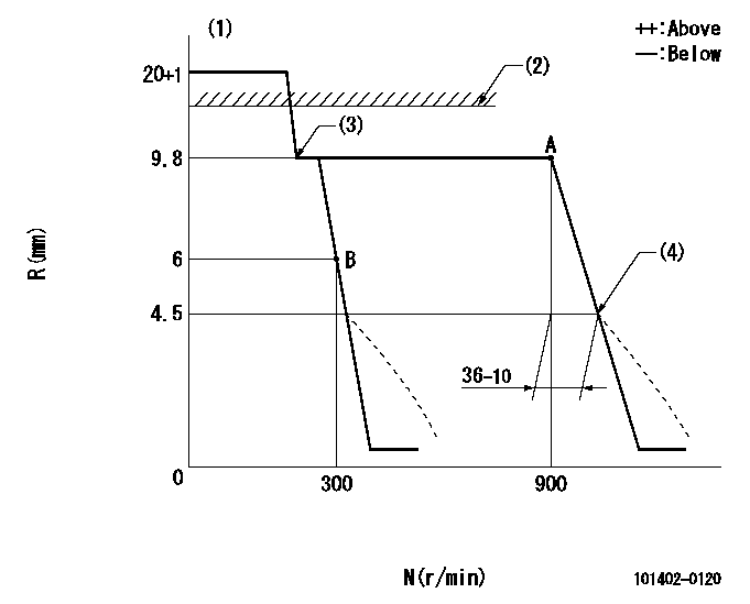
N:Pump speed
R:Rack position (mm)
(1)Target notch: K
(2)At rack cap installation: R1
(3)The torque control spring does not operate.
(4)Idle sub spring setting: L1.
----------
K=12 R1=(17.5)mm L1=4.5mm
----------
----------
K=12 R1=(17.5)mm L1=4.5mm
----------
Speed control lever angle
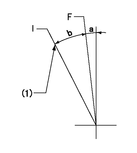
F:Full speed
I:Idle
(1)Fix idle side stopper bolt.
----------
----------
a=12deg+-5deg b=(23)deg
----------
----------
a=12deg+-5deg b=(23)deg
Stop lever angle

N:Pump normal
S:Stop the pump.
----------
----------
a=19deg+-5deg b=53deg+-5deg
----------
----------
a=19deg+-5deg b=53deg+-5deg
Timing setting

(1)Pump vertical direction
(2)Position of gear mark 'CC' at No 1 cylinder's beginning of injection
(3)B.T.D.C.: aa
(4)-
----------
aa=16deg
----------
a=(90deg)
----------
aa=16deg
----------
a=(90deg)
Information:
Illustration 13 g02915447
Plugged DOC
The DOC utilizes a “pass-through” technology, which is different from the “wall flow” design of a DPF. When a light is shined through the DOC, a visible light should be able to pass through. Utilize a flashlight to check for a plugged DOC face. Aim the flashlight into the DOC inlet, visible light should be seen through the DOC. A plugged DOC can be caused by high oil consumption, not recommended fuel additives, or wrong engine oil types. Refer to the Operation and Maintenance Manual for recommended fluids to use. If light cannot be seen on the outlet of the DOC, then replace the DOC.CRS Bodies
Illustration 14 g06342815
Combustion Group
(1) Head Group - Combustion
(2) Gasket
(3) Tube
(4) Body Assembly - Exhaust CombustionCRS Combustion Body (4) contains the flame necessary for CRS Regeneration. There are two combustion stages that occur within the CRS Body: the primary and secondary combustion. The primary combustion of air and fuel occur within Tube (3) to create the CRS flame immediately following Head Group (1). The secondary combustion of the CRS flame and exhaust gas from the turbocharger occur within Body Assembly (4).The body assembly is the only salvageable part of the combustion group. The body assembly must be cleaned, inspected, and pressure tested prior to reuse.Cleaning
Start by isolating the CRS body from all other CRS exhaust components. Remove the head group, the mounting studs, the tube, and the two gaskets.The gasket area and the bellows joints are the two areas of the CRS body that must be cleaned thoroughly to make a proper seal.Cleaning the remainder of the CRS body is not required. If cleaning the CRS body is desired, then first perform the visual inspection, vacuum inspection, and welding procedures prior to washing the CRS body. This step is to ensure that the CRS body is salvageable, not cracked, and to keep water from getting trapped behind the heat shield.If washing is preferred, then use soap and water as a cleaning solution. Do not submerge the CRS body to prevent water from becoming trapped between the heat shield and the CRS body. A cylinder washing brush, a wire brush with handle, and a greenScotch Brite pads are all acceptable cleaning equipment. Removal of all diesel particulates is not required for inspection.
Do not use any combustible solvents to clean the CRS body.
Visual Inspection
A visual inspection of the CRS body must be completed, special equipment or crack detecting solution is not required. Visually inspect the exterior of the CRS body. Small cracks and/or punctures found on the stainless steel heat shield is normal and should be expected. Inspect the bellows sealing joints and the CRS head mating surface for visual damage.Light surface rust is typically not a problem unless rust is found on a bellows joint or the CRS gasket mating surface. Light rust in these two areas must be removed using a Scotch Brite pad.Serviceability
All bolts, studs, and clamps are not reusable and must be replaced with new components.Any thread damage in the mounting
Have questions with 101402-0120?
Group cross 101402-0120 ZEXEL
Isuzu
101402-0120
5156006813
INJECTION-PUMP ASSEMBLY
4BB1
4BB1