Information injection-pump assembly
ZEXEL
101401-9771
1014019771
NISSAN-DIESEL
1670019D61
1670019d61
Rating:
Cross reference number
ZEXEL
101401-9771
1014019771
NISSAN-DIESEL
1670019D61
1670019d61
Zexel num
Bosch num
Firm num
Name
Calibration Data:
Adjustment conditions
Test oil
1404 Test oil ISO4113 or {SAEJ967d}
1404 Test oil ISO4113 or {SAEJ967d}
Test oil temperature
degC
40
40
45
Nozzle and nozzle holder
105780-8140
Bosch type code
EF8511/9A
Nozzle
105780-0000
Bosch type code
DN12SD12T
Nozzle holder
105780-2080
Bosch type code
EF8511/9
Opening pressure
MPa
17.2
Opening pressure
kgf/cm2
175
Injection pipe
Outer diameter - inner diameter - length (mm) mm 6-2-600
Outer diameter - inner diameter - length (mm) mm 6-2-600
Overflow valve
134424-4120
Overflow valve opening pressure
kPa
255
221
289
Overflow valve opening pressure
kgf/cm2
2.6
2.25
2.95
Tester oil delivery pressure
kPa
157
157
157
Tester oil delivery pressure
kgf/cm2
1.6
1.6
1.6
Direction of rotation (viewed from drive side)
Right R
Right R
Injection timing adjustment
Direction of rotation (viewed from drive side)
Right R
Right R
Injection order
1-3-4-2
Pre-stroke
mm
3.2
3.15
3.25
Rack position
Point A R=A
Point A R=A
Beginning of injection position
Drive side NO.1
Drive side NO.1
Difference between angles 1
Cal 1-3 deg. 90 89.5 90.5
Cal 1-3 deg. 90 89.5 90.5
Difference between angles 2
Cal 1-4 deg. 180 179.5 180.5
Cal 1-4 deg. 180 179.5 180.5
Difference between angles 3
Cyl.1-2 deg. 270 269.5 270.5
Cyl.1-2 deg. 270 269.5 270.5
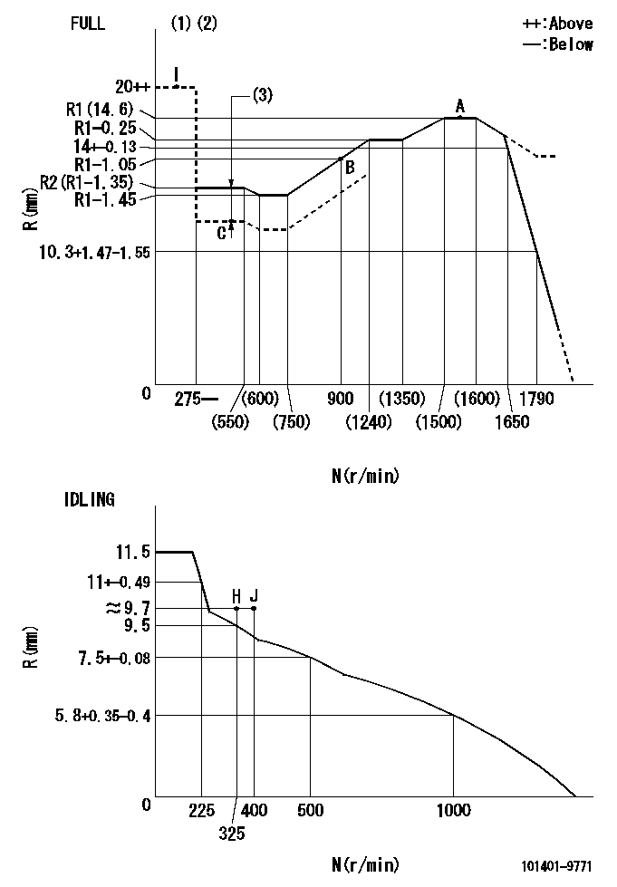
Injection quantity adjustment
Adjusting point
-
Rack position
14.6
Pump speed
r/min
1550
1550
1550
Average injection quantity
mm3/st.
108.5
106.9
110.1
Max. variation between cylinders
%
0
-3.5
3.5
Basic
*
Fixing the rack
*
Standard for adjustment of the maximum variation between cylinders
*
Injection quantity adjustment_02
Adjusting point
H
Rack position
9.7+-0.5
Pump speed
r/min
325
325
325
Average injection quantity
mm3/st.
13
11.2
14.8
Max. variation between cylinders
%
0
-10
10
Fixing the rack
*
Standard for adjustment of the maximum variation between cylinders
*
Injection quantity adjustment_03
Adjusting point
A
Rack position
R1(14.6)
Pump speed
r/min
1550
1550
1550
Average injection quantity
mm3/st.
108.5
107.5
109.5
Basic
*
Fixing the lever
*
Boost pressure
kPa
70.6
70.6
Boost pressure
mmHg
530
530
Injection quantity adjustment_04
Adjusting point
B
Rack position
R1-1.05
Pump speed
r/min
900
900
900
Average injection quantity
mm3/st.
88
84
92
Fixing the lever
*
Boost pressure
kPa
70.6
70.6
Boost pressure
mmHg
530
530
Injection quantity adjustment_05
Adjusting point
C
Rack position
R2-0.95
Pump speed
r/min
500
500
500
Average injection quantity
mm3/st.
58
54
62
Fixing the lever
*
Boost pressure
kPa
0
0
0
Boost pressure
mmHg
0
0
0
Boost compensator adjustment
Pump speed
r/min
500
500
500
Rack position
R2-0.95
Boost pressure
kPa
10.7
9.4
12
Boost pressure
mmHg
80
70
90
Boost compensator adjustment_02
Pump speed
r/min
500
500
500
Rack position
R2(R1-1.
35)
Boost pressure
kPa
57.3
57.3
57.3
Boost pressure
mmHg
430
430
430
Timer adjustment
Pump speed
r/min
1000--
Advance angle
deg.
0
0
0
Remarks
Start
Start
Timer adjustment_02
Pump speed
r/min
950
Advance angle
deg.
0.5
Timer adjustment_03
Pump speed
r/min
1550
Advance angle
deg.
5.1
4.6
5.6
Timer adjustment_04
Pump speed
r/min
-
Advance angle
deg.
7
6.5
7.5
Remarks
Measure the actual speed, stop
Measure the actual speed, stop
Test data Ex:
Governor adjustment
N:Pump speed
R:Rack position (mm)
(1)Torque cam stamping: T1
(2)Tolerance for racks not indicated: +-0.05mm.
(3)Boost compensator stroke: BCL
----------
T1=L33 BCL=0.95+-0.1mm
----------
----------
T1=L33 BCL=0.95+-0.1mm
----------
Speed control lever angle
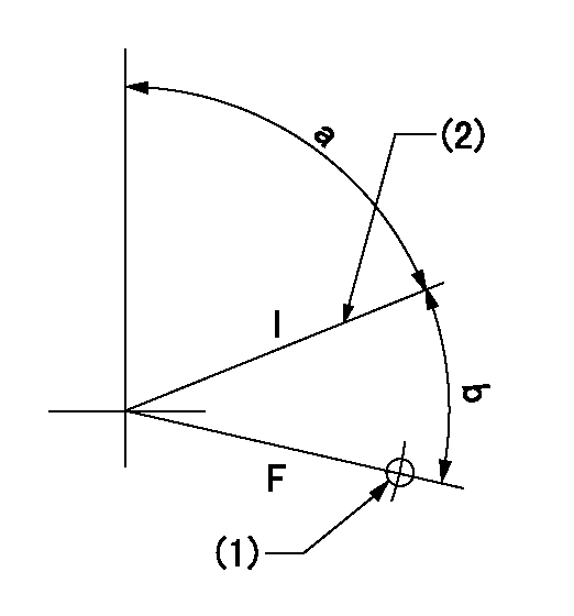
F:Full speed
I:Idle
(1)Use the hole at R = aa
(2)Stopper bolt set position 'H'
----------
aa=32mm
----------
a=71deg+-5deg b=(38deg)+-3deg
----------
aa=32mm
----------
a=71deg+-5deg b=(38deg)+-3deg
Stop lever angle

N:Pump normal
S:Stop the pump.
(1)Use the pin at R = aa
----------
aa=15mm
----------
a=29deg+-5deg b=10deg+-5deg
----------
aa=15mm
----------
a=29deg+-5deg b=10deg+-5deg
0000001501 LEVER
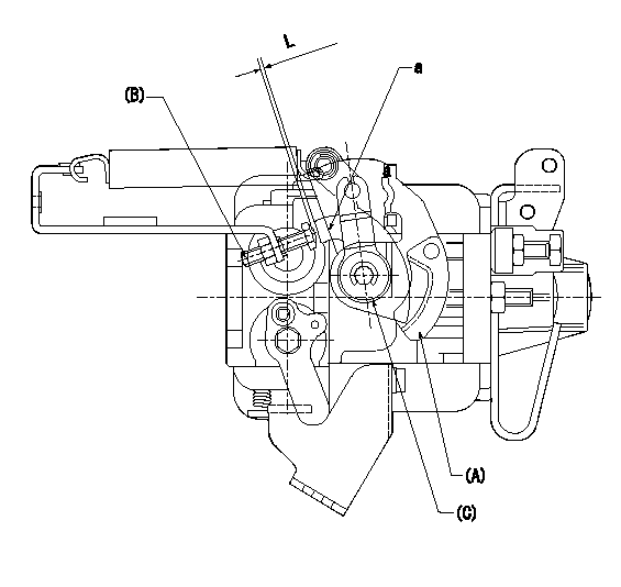
(A) Speed lever (lower)
(B) Stopper bolt
(C) Special lever (upper)
a:Point A (inside lever)
1. Special lever adjustment
(1)With the speed lever at the idle position, set the accelerator lever stopper bolt so that the accelerator lever contacts the speed lever at point a.
(2)Back off the stopper bolt L and set.
----------
L=1+0.5mm
----------
----------
L=1+0.5mm
----------
0000001601 POTENTIO METER
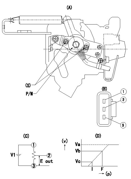
(A) : Governor plan view
(B): Potentiometer harness terminal
(C): Potentiometer connection diagram
(D) : Output voltage standard value
(S): Voltage
P/M: potentiometer
(v): output voltage (V)
(p): direction of potentiometer rotation
1. Adjustment procedures
(1)Apply DCV1 to potentiometer harness terminal (B) to obtain the specified output voltage.
(2)Fix the speed lever at the full side.
(3)Loosen the bolt (S), and move the potentiometer from left and right.
(4)Adjust so that the output voltage at full is within the standard values.
(5)Fix bolt (S).
(6)Repeatedly move the speed lever from the full side to the idle side.
(7)Check that it is within the standard values at full and idle.
----------
V1=5+-0.02V
----------
V1=5+-0.02V Va=(5)V Vb=(3.75)+-0.2V Vc=0.58+-0.3V
----------
V1=5+-0.02V
----------
V1=5+-0.02V Va=(5)V Vb=(3.75)+-0.2V Vc=0.58+-0.3V
Timing setting

(1)Pump vertical direction
(2)Position of gear's standard threaded hole at No 1 cylinder's beginning of injection
(3)B.T.D.C.: aa
(4)-
----------
aa=5deg
----------
a=(50deg)
----------
aa=5deg
----------
a=(50deg)
Information:
Introduction
***#i00660713/i00660713*** contains the abbreviations, symbols, wiring sizes, wiring color and number codes for the ETR/ETS electric protection system which are placed on drawings and wiring, and referenced in the text of this Service Manual.The electrical system for the engine contains five subsystems. Each subsystem has different symbols and wire number codes. Abbreviations, symbols, numbering and lettering codes, and wiring requirements are described for the following subsystems.
Starting
Charging
Control
Monitoring
ProtectionThe engine electrical system is designed to improve operational reliability, reduce maintenance problems, improve the flexibility for making changes or additions to the system, and comply with international standards. In order to accomplish these goals, the engine electrical system contains the following components.
A steel junction box for the control, monitoring, and protection subsystems with standardized mounting locations on each engine series.
A steel power distribution box for the high amperage starting and charging subsystems with standardized mounting locations on each engine series.
A wiring harness in a protective nylon conduit that connects the junction box, power distribution box, and the electrical components located on the engine.
Common heat stamped wire number codes on each wire in the wiring harness for all engine models.
Common logic for all subsystems on all engine models."Description of Electrical System Symbols And Codes" explains how to use and understand the graphical representation of the ETR/ETS electric protection system by component and wiring abbreviations, symbols, and codes.Description of Electrical System Symbols And Codes
The Point-To-Point graphical system is used in all the wiring diagrams and schematics which help describe the systems operation and troubleshooting of the ETR/ETS electric protection system.Each wire in the wiring harness is heat stamped the length of the wire with the wire number code as shown in the ETR/ETS Wiring Using Wire Number Codes diagram on Illustration 7. The first number pair of the wiring code identifies the terminal on an engine component to which one end of the wire should be attached. The second number pair of the wiring code identifies the terminal on the component to which the other end of the wire should be attached. The number assigned to each terminal of each component will be the same for all engine models.The two numbers in the wiring code differentiate between left and right hand mounting. Illustration 2 contains the Number Codes and an example of usage.The symbols for the engine components will be the same for all 3200-3500 Series Engines.The use of abbreviations, symbols, and codes is provided by the following example. In order to locate and identify the wire which connects the starting motor magnetic switch and the starting motor, first determine the correct drawing abbreviation. The Abbreviation List on Illustration 1 shows ("SMMS") as the abbreviation symbol for the starting motor magnetic switch. ("SM") is shown as the abbreviation symbol for the starting motor. The symbols for both the starting motor magnetic switch and the starting motor are listed under the Starting System on 3.Locate the ("SMMS") and ("SM") symbols on the Starting System list on Illustration 3. Because an engine option exists for two